Carving Out Your Schematic in OrCAD PCB Designer
Key Takeaways
-
Using OrCAD Capture to place components on a schematic
-
Drawing nets and buses to route schematic connectivity
-
Cleaning up the schematic in OrCAD PCB Designer
A multi-sheet schematic in OrCAD Capture
While a movie may be filmed, a song is recorded, or an article is drafted, the creation of electronic connectivity data for a printed circuit board is known as capturing the schematic. At one time schematics were first drawn by hand and then later on “captured” in a PCB design schematic CAD system. Although this process is now outdated, the creation of electronic designs still involves concepts, ideas, research, experimentation, and finally drawing the schematic. To compile all of this work together into a design still deserves the phrase “schematic capture,” and capturing a schematic in OrCAD PCB designer is one of the best tools that you can do this with.
OrCAD Capture is an advanced user-friendly PCB design system to work with and has a long history of successfully being used for all levels of design technology. As the industry standard for schematic capture tools, OrCAD also has plenty of different capabilities allowing it to fulfill any role that it is being used for. To help you understand how OrCAD is used for schematic capture, we are going to outline some of the basic features and workflow in this article. By the time we are finished, you will have a better grasp of how to use OrCAD for placing and wiring components in a schematic.
Placing Components on the Schematic in OrCAD PCB Designer
OrCAD capture works together with OrCAD layout, and before the design is started both systems must be configured for their user preferences. Because they are designed to work together, many of the setup parameters and configurations will be similar between the two. An example of the settings in the schematic editor is shown in the picture below:
Some of the preference settings available to the user in OrCAD Capture
Another configuration aspect of the tools that have to be set up is their links and library paths. Both the schematic and the PCB editors have the capabilities to access a wide variety of libraries, including external third party part provider systems which will be discussed in a moment. They also can be configured to access standard user and corporate symbols and PCB footprint libraries.
With the design set up and ready to go, it’s time to capture the schematic. We will start with the assumption that the design already exists with a schematic object in it, and that OrCAD Capture has been opened on it. The schematic will already have a blank page in it for working with, but to open a new page, right-click on the schematic object in the design hierarchy tree, and select “New Page.” You will have the option to give the new page any name you desire.
To begin placing components, go to the pulldown menu Place > Part, click the place part icon, or type a “p” on the keyboard. This will pop the part menu up, if it isn’t already visible, giving you access to the symbols and parts that you can place. Before a component can be placed however, the appropriate libraries must be added as we stated earlier. If the parts list is empty, click on the green add libraries button in the libraries menu below the Part List menu, and navigate to the library that you want to add. Now you can begin placing component symbols on your schematic sheet.
Double click on the component listed in the Part List menu, and it will appear floating on your mouse cursor. While it is floating you can press the “r” key on the keyboard to rotate it. Once you have it positioned where you want it, click the mouse again to place it down. Note that another instance of the same part will appear on your cursor waiting for you to place it as well, which can save a lot of time when placing repetitive parts. To get out of the placement mode for that part, hit the escape key.
You can also select a component to place from a third-party resource as we mentioned earlier. To do this, go to the Place > Search Providers pulldown menu and sign in to your accounts. Once you are logged into your account, you can see the list of components available from the parts providers that you have access to. These providers will offer component information with datasheets, symbol files, footprint files, and STEP models. You have the ability to search for specific parts or to set up filters to show types or classifications of parts. By right-clicking on the part, you can download it into your design and place it directly on your schematic sheet as shown in the picture below. Additionally, once the part is active on your cursor you can rotate and place it as you would when placing a component out of your regular libraries.
With the symbols placed on your schematic, you can now edit these components depending on how you need to arrange and configure them.
Placing a component symbol in OrCAD using the Part Provider menu
Editing Placed Components on an OrCAD Schematic
Once the part is placed on the schematic, you can edit and manipulate it depending on the needs of the design. By double-clicking on the part you will bring up the property editor for it. By scrolling through the editor window horizontally, you can see design information such as part numbers, vendors, and values, as well as CAD data such as reference designators and PCB footprints. Many of these values can be changed as well such as the PCB footprint or the color. In the picture below you can see an example of the property editor opened on a selected symbol.
The property editor opened on a selected part in an OrCAD schematic
To move a placed component, simply hold the mouse button down while hovering over it, and move the part to the new location. While moving the part you can rotate it as you did before with an “r” from the keyboard. You also have a lot of other options by selecting the part and right-clicking on it to bring up its edit menu. Here you can rotate it, edit the base symbol, view the footprint, mirror it, as well as many other operations such as copy and delete.
With the component symbols placed and organized on the schematic now, you are ready to start wiring up the connections between them in order to add the net connectivity needed for layout.
Connecting Nets Between Components
To start drawing a wire, go to the Place > Wire pulldown menu, click the wire button in the toolbar, or type a “w” on the keyboard. Click on a component pin, and the wire will start following your cursor. As you draw, you will notice that the wire will automatically create a 90-degree corner to follow a change in mouse direction, but the corner won’t stick until you click the mouse button. To finish routing the wire, click on the destination pin. The wire will be complete, but it will still remain in the add wire mode to draw again until you hit the escape button.
To add a series of short wires to connect for ground connections or a bus, draw the short wire into the top pin of a series of pins and double click to finish the wire. Now use the F4 button to add the last wire segment that you drew into each pin below it. Make sure to use the escape button to get out of the mode when you are finished.
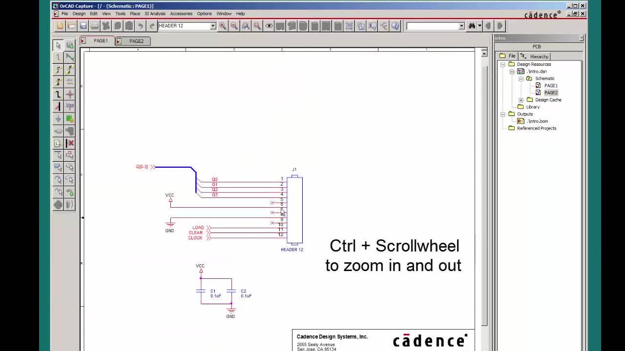
Drawing a bus in OrCAD is just as simple as a wire with the commands again being in the Place pulldown menu, the toolbar, or by typing a “b” on the keyboard. Draw the bus close to the short lines that you created earlier, and when finished use the add bus entry command or “e” on the keyboard to connect them together. Bus entries can be added by clicking on the end of each wire to be connected, and you can rotate them with the “r” key while you are adding them if necessary.
Another method of connecting nets into the bus is to use the auto-connect feature in the pulldown menu or the toolbar. Once enabled, click all the wires that you want to connect first, and then the bus. You will then be prompted to enter net names in a pop-up menu. In the picture below, the upper bus was created with copied net lines and bus entries, while the lower bus was created using the auto connect feature. At this point, your wires and buses may not look as organized as you like, but they can be cleaned up and edited with the features that we will look at next.
The top bus was connected with bus entries, while the bottom was connected with auto connections
Editing Net Connections on Your Schematic
With the components placed and the nets drawn, your initial schematic work is nearly complete, but you will also need to name your nets before the design will be ready for layout. This can be done with the Place > Net Alias pulldown menu, the toolbar button, or by hitting an “n” on the keyboard. As with placing any other object, the net alias can be rotated with the “r” key as you are moving them around, and the net that it is placed on will take that alias as its net name. By using a number on the end of the net alias, the net names will roll recursively to the next number as you place each name, which you can see in the picture below. Another important point about net aliases is that by putting a name on a net, OrCAD will identify that net as being connected even if it isn’t drawn to a pin. This can be very useful when connecting many nets to GND or other large common nets.
Assigning net names with the net alias command in OrCAD Capture
At this point, you may need to move some circuitry around to organize your final schematic, and OrCAD makes this job simple with its editing capabilities. By selecting a component or a segment of wire and holding the mouse button down on it, you can move it to wherever you need. Wire segments that are moved will automatically adjust as you move them, and components will drag their wires along with them. To move large sections of circuitry, simply hold your mouse button down and draw a rectangle around the desired circuitry to select it. Once selected, the circuitry can be moved in the same way as an individual component or wire.
There is much more to capturing and editing a schematic, but this brief introduction will give you the basic idea of how much OrCAD Capture is designed to help you. For more information on design creation and schematic capture, take a look at this E-book.
If you’re looking to learn more about how Cadence has the solution for you, talk to us and our team of experts.