06 - Exploring Part Manager Window
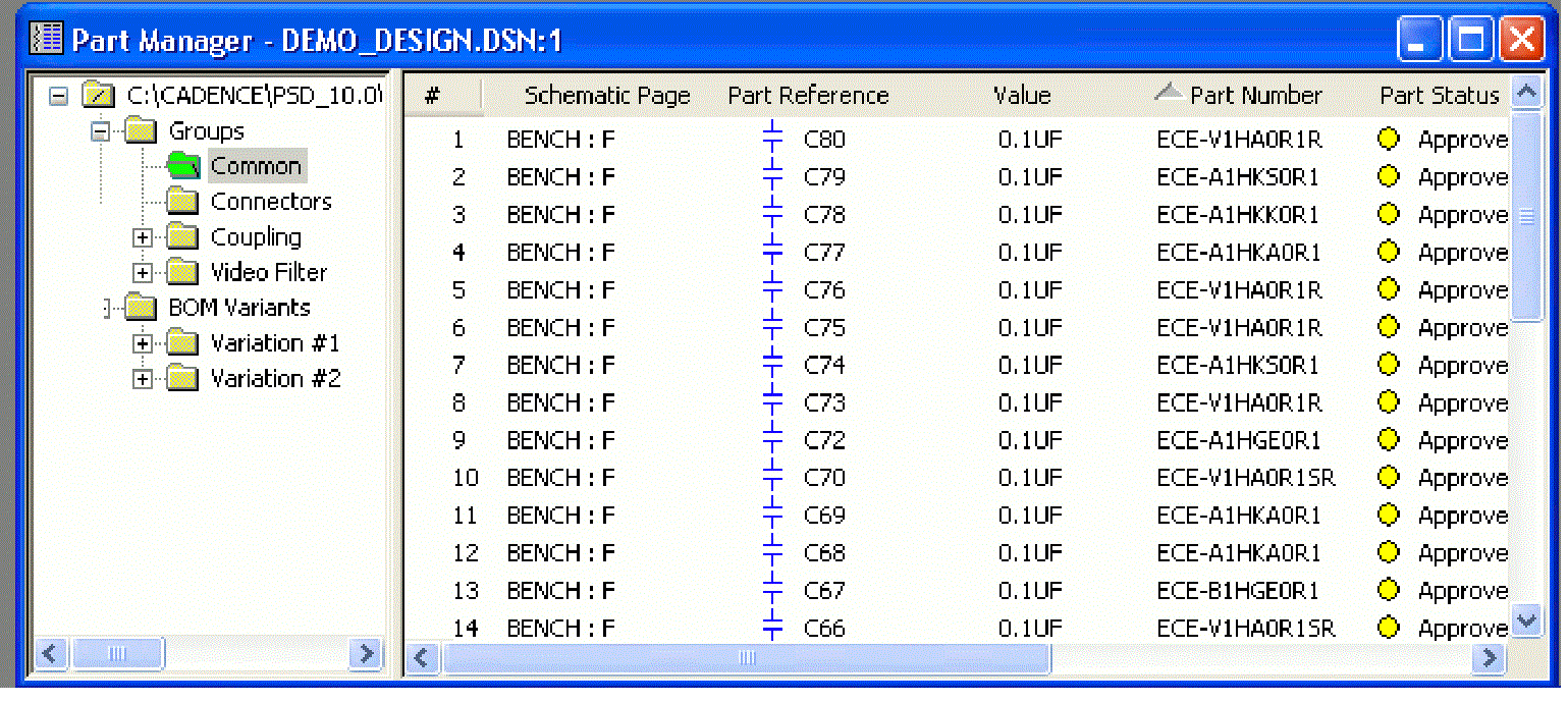
The part manager's tree view provides a graphical interface for easily creating groups, subgroups, and BOM variants for your core design. Within the tree view, you can link a database part or update a part's status. You can link and view a part or update its status from within a group, but you cannot update a database part from within a BOM variant folder. The part manager contains two separate panes: a tree view on the left, and a list view on the right. You can adjust the work environment for the part manager.
Tree View Structure
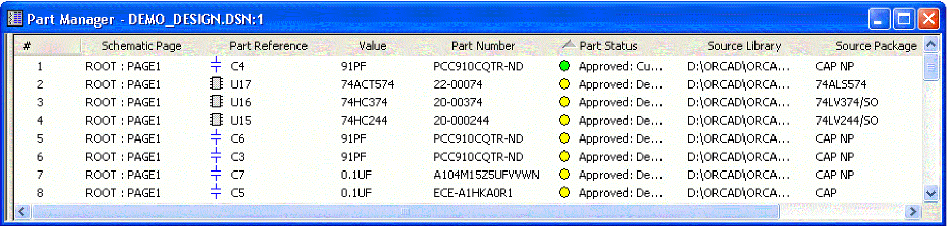
At the top level of the tree view, there is the root folder that displays the path to the core design. When selected, the right side pane displays all of the components in the core design. Any modifications made to components at this level results in a change in the core design.
Under the tree view, there is a folder called Groups. You create all your groups and subgroups under this folder. The Groups folder contains all the groups that have been created on the current design. When the Groups folder is selected, the right side pane displays all groups that are available.
The Folders
Under the root folder, there are Groups, subgroups, and the BOM Variants folders.
Groups
In a design, multiple components are used to support a particular functionality or module. For example, power module, memory, or resolution. Whenever the module needs to be changed, all the individual components of that module also change. Groups make variant creation easier and closer to the way it is done in real life. Groups are subsets of components that can be used when creating variants.
Subgroups
Groups can be further divided into subgroups. A subgroup contains components that are required for different versions of the groups. For example, if you have a group called Power, the components in that group may differ depending on whether you wish that module to be used in the UK or the US. You cannot drag components to a subgroup. Instead, you must drag the components into the group, which will then populate all subgroups.
The Common folder
The Groups folder also contains a folder called Common. This folder stands out in the tree view structure because of its green color. Also, it is always the first folder under the Groups folder. Initially, the Common folder contains all of the components in a design. As components are placed into groups or subgroups, they are removed from the Common folder.
From the Common folder under the Groups folder, you can use three commands: View Database Part, Update Selected Part Status, and Update All Part Status. The View Database Part and Update Selected Part Status commands are only available when a component is selected in the right side pane. The Update All Part Status command is always available.
You can drag the Common folder into the BOM Variant folders. These folders will contain the same content as the Common folder under Groups.
The BOM Variants folder
You can modify components to use with BOM variants, and store the variations in folders in the part manager tree view. Under the BOM Variants folder, you create design variants from the groups and subgroups that you created. The BOM Variants folder contains all the BOM variants that you create on the current design. When the BOM Variants folder is selected, the right side pane displays all BOM variants that you have created.
You can create a new BOM variant by selecting the New BOM Variant command from the Edit menu keeping the BOM Variants folder selected. This command displays a dialog box, which prompts you to enter a name for the new BOM variant. A folder is added to the tree with the name that you specify. By default, the new BOM variant contains all of the components in the core design.
You can populate a BOM Variant with components by dragging them from the folders under the Groups folder. The Common folder is dragged in with the same name. If you drag a group, the folder remains the same. If you drag a subgroup, the name of the group is added as prefix to the subgroup name (groupName_subgroupName). You cannot update a component from the BOM variant, although the variant mark column will always be displayed from this level.
The Commands
These commands are available only when a component is selected in the right side pane. The Update Part Status command is always available and is performed on the core design.
Link Database Part Command
Link Database Part is available when a component is selected in the right side pane in the root folder or in any of the groups or subgroups. If you use the Link Database Part command from the root folder, the core design is updated. As a result, the components on the schematic page are replaced by the components that you choose from the database. Similarly, if the command is used from a group or a subgroup, the component will be updated in all occurrences of that group or subgroup. For example, If you link a part in the Power US subgroup which has also been dragged into the BOM Variants folder called US, the change will also be reflected in the BOM variant. Further, if the Link operation is performed from a group or a subgroup and the new component has a footprint different from the part in the core design, you will get a warning message stating that the footprint differs from the core design.
The Link Database Part command is available when a single component or multiple components have been selected. Each selected component is linked to the new part selected in the database. The Link Database Part command invokes the CIS Explorer window. The CIS Explorer will by default query for parts in the database that have the same value.
View Database Part Command
When you choose the View Database Part command, the CIS Explorer window is invoked and the selected part is displayed. The View Database Part command is available only if one component is selected in the list view. The CIS Explorer will, by default, query for parts in the database that have the same Part Number. If the selected part does not exist in the database, a blank CIS Explorer window is displayed.
Update Selected Part Status Command
The Update Selected Part Status command is used to ensure that the selected part in the design exists in the part database. Furthermore, it resolves any differences between part property values and their corresponding database property values.
Update All Part Status Command
The Update All Part Status command is used to ensure that all the parts in your design exist in the part database and resolve any differences between part property values and their corresponding database part property values. This command works exactly like the Update Selected Part Status command, difference being this command works on all the parts in the design.
Displaying Toolbar and Tree View
The part manager toolbar offers a quick and easy way to perform common tasks, such as linking database parts, updating part status, expanding or collapsing the tree structure, etc. A gray tool button indicates that you cannot perform that task in the current situation.
To display the toolbar, do the following:
- From part manager’s View menu, choose Toolbar.
- To hide the toolbar, do one of the following:
- If the toolbar is floating (not docked), click the hide button in the top corner of the toolbar.
- From part manager’s View menu, choose Toolbar.
- Move or dock the toolbar as desired.
- To display the name of a toolbar button command, point at the button briefly.
You can choose to display or hide the tree view using the Show/Hide Tree View command.
Expand or Collapse the Folder Hierarchy in the Tree View
You can also expand or collapse an entire branch of folders in the tree view hierarchy, removing the need to expand or collapse each subfolder individually using the Show/Hide Tree View command from the View menu in Part Manager.
This command toggles between expanded and collapsed display of folders in the part manager tree view.
Viewing Part Status
To view the part status, you need to open the Part Manager that shows all parts in the design, sorted by part status.
Opening Part Manager
When you open the Part Manager window, CIS generates a report describing the status of your design’s placed parts the last time they were checked against the database parts. If you have changed part properties on any placed parts or placed any non-database parts since the last time you updated part status, the report generated when you open the part manager will not reflect the current status of your design with respect to the database.
To open the part manager, do the following:
- Open a new or existing schematic design.
- From the Tools menu, point to Part Manager and choose Open. CIS displays the part manager, showing all parts in the design, sorted by part status.
If no configuration (.DBC) file has been specified for use with the part manager, no information will be displayed in these columns when you open the part manager for the first time.
Updating Part Status
You can update the part status for your design using the part manager. When you update your part status in the part manager, CIS checks all the placed parts in your design against the part database, and updates part properties where necessary.
Any properties that you have assigned to part instances are retained when you update part status for your design, even if they differ from the values in the database.
For example, assume that an AND gate part in your database has a Part Number value of 456 . Suppose that you assign a Part Number value of 123 to an instance of an AND gate in your design. That Part Number value applies only to that particular instance of the AND gate. When you update part status, CIS assigns the Part Number value 456 to all instances of the AND gate except that instance, which retains the value 123.
You can also view an individual part's local and Internet database properties.
To update part status for your design, do the following:
- Open a new or existing schematic design.
- Update the part status for specific parts or for your entire design.
To update the part status for specific parts, select the parts in the project manager window and from the part manager’s Tools menu, choose Update Selected Part Status.
To update the part status for your entire design, do one of the following:- From the Tools menu, point to Part Manager and choose Update.
- From the part manager’s Tools menu, choose Update Part Status.
CIS checks each placed part against the database part to which it is linked. The part database is searched for the Part Number property that matches the placed part, then transferred properties that are configured to be updated are compared.
If you want to make sure that none of your parts have been modified since they were placed from their original libraries, from the Options menu in part manager, point to Update Part Status and choose Verify Parts Against Libraries (.OLB). Then, when you update part status, any placed part with a different timestamp than its library part will be flagged yellow.If you turn on the Verify Parts Against Libraries (.OLB) option when you have placed parts in the design using a previous version of CIS (Release 9.0 or earlier), all parts placed from the previous Capture libraries will have mismatched timestamps and be flagged yellow. If you get an undesirable result, turn off the Verify Parts Against Libraries (.OLB) option and update part status again.
For each placed part that is not current, you are prompted with the Update Part dialog box. This dialog box lets you decide whether or not you want to update the placed part properties with the transferred properties from the database part.
The first row lists the database part and its properties, and the second row lists the placed part and its properties. The differences between the database part and placed part are highlighted in red.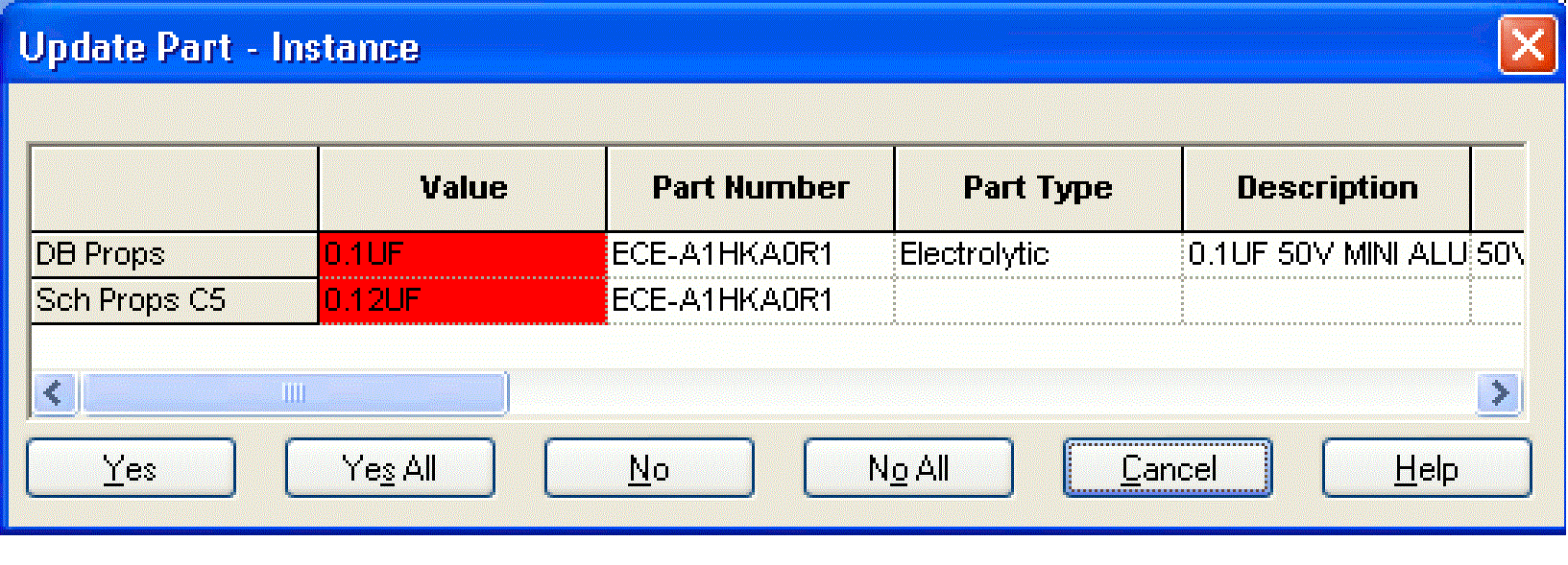
-
Click one of the following buttons:
Button Action Yes
Update the placed part.
Yes All
Update all placed parts whose properties don’t match the database part properties.
No
Not update the placed part.
No all
Not update any of the placed parts whose properties don’t match the database part properties.
In some cases, CIS cannot automatically determine the correct database part with which to refresh the placed part. In these cases, you must wait until the update is complete and link the placed part to a database part.
If you get the error message: "Schematic Parts "X" and "X" are not the same" while updating the part status, then make sure that you compare the source library entry in the Source Library column of the Property Editor with the source library of the database that is being referenced by the Schematic Part column of the CIS database.
When complete, a list of updated parts and discrepancies with the database is written to the session log. Then, the part manager window displays the updated part status. The Part Status column contains both text and color-coded icons that indicate whether your placed part is linked to a part in a part database. The following table lists all the possible status conditions and what the each status condition means.
|
Status |
Part Behavior |
|---|---|
|
Green icon |
Is approved and current |
|
Yellow icon |
Is in the approval process |
|
Red icon |
Would be incorrect if you generated a BOM |
|
Approved |
Has a defined part number property type |
|
Temporary |
Has a temporary part number |
|
Undefined |
Has no part number property |
|
Current |
Has transferable properties matching those of the database part |
|
Defined |
Has a part number property |
|
Undefined part reference |
Has an undefined part reference |
|
Not current |
Has at least one transferable property that does not match the database part properties. |
|
Duplicate |
Has a part number that occurs more than once in the part database |
|
Not found |
Has a part number that does not exist in the part database |
If your configuration specifies that CIS assign temporary part numbers automatically, each status is preceded by either Temporary Part (if the placed part number prefix is the temporary part number prefix) or Approved Part.
When the status of all the parts in your design is Current, you are ready to generate a report such as a bill of materials.
Once you have updated part status, the part manager also includes tips for parts with a red icon status. The tips give more detail about the part’s status and about placed part properties that do not match the database part properties. To display a tip, point briefly over the status column.
The part status is based only on the part properties you have specified to be transferred from the part database. Other properties that may reside in the part are not checked.
To remove variant properties from a linked component, do the following:
- In the part manager tree view, select the group or subgroup folder that contains the part you want to change.
- In the part manager list view, select the component from which you want to remove linked properties.
- From the part manager window’s Edit menu, choose Revert to Common. The check mark no longer appears next to the component, indicating that the linked properties have been removed.
Saving the Status Report
You can save the contents of the part manager window to a text (.PRP) file. The report file is saved (in the current sort order) in tab-delimited format which can be edited with a spreadsheet program or word processor.
To save a status report, choose one of the following options:
| Step | Option |
|---|---|
|
Save the report file using the name of your design file. |
From the File menu, select Save. Example: If your design’s filename is MYDESIGN.DSN, CIS automatically names your report MYDESIGN.PRP when you choose the Save command. |
|
Save the report file using the name of your choice |
From the File menu, select Save As. |
View the next document: 07 - Groups, Subgroups, and BOM Variants
If you have any questions or comments about the OrCAD X platform, click on the link below.
Contact Us