Routing with Allegro PCB Editor
Key Takeaways
-
Setting the design up for printed circuit board trace routing.
-
Trace routing features and functions used by PCB designers.
-
The advanced routing capabilities of the design tools.
Allegro PCB Editor makes routing easy - just sketch the path you want to take with scribble routing and maintain proper clearance!
When PCB layout tools were first introduced, they weren’t much better for routing traces than using an etch-a-sketch. You would draw lines that would be associated with intelligent nets but the editing capabilities were slight, they lacked much in the way of design rules, and there was little automation available for help. As design systems have improved over the years, though, the capabilities of trace routing have grown exponentially with all kinds of new features and functions.
While these routing enhancements are a welcome relief for designers faced with complex layouts to route, they also require an understanding of how best to use them. For example, Allegro PCB Editor from Cadence is armed with many innovative features that give designers a lot of options for routing their boards. In fact, there is so much routing functionality in Allegro that some users need help in getting started with it. If you’ve found yourself in the position of wanting to know more about PCB routing with Allegro, you’re in the right place and we have the answers here that can help you.
Setting up for Routing in Allegro PCB Editor
Before you can start routing in Allegro, you need to be set up for it. There are several different parameters that can be adjusted, from rules and constraints to display settings and routing behaviors. We will start first with the design rules and constraints.
Although you can route in Allegro using the default settings for trace widths and spacings, you will find yourself having to constantly change those values as you route different nets in your design. You may even run into performance and manufacturability problems due to spacing errors if you don’t have all the rules in place. Using the built-in rules and constraints in your design system allows you to set up multiple trace widths, as well as clearances for pins, vias, nets, net groups, or other board objects. These rules and constraints can also be entered while working on the schematic and then sent over to the layout when you synchronize the design database.
Allegro PCB Editor comes with an advanced Constraint Manager system that gives you complete control over all of the design rules of the design. For routing traces, this is invaluable as you can set up different trace widths and clearances for individual nets, net groups, certain layers, and even specific regions of the board. Your data entries will be entered into the Constraint Manager’s spreadsheet-style interface, which will then govern how the board will be routed.
The next parameters to set up are those that will control how the design looks and behaves in the PCB Editor window. These settings can be accessed through the “Display” and “Setup” pulldown menus, but the easiest access is to use the “Design Workflow” menu, as shown in the picture below. As you can see, there are menus for the design parameters, grids, and display colors.
Some of the parameters to be set up in Allegro for routing.
The ”Grids” menu allows you to refine the grid settings to suit your routing requirements. The “Colors” menu not only allows you to set up the colors for each layer but also gives you more specific control over individual elements being displayed. For instance, it gives you the ability to change the visibility and color of the silkscreen component outlines and reference designators separately. The “Design Parameters” menu gives you control over different aspects of the design in separate tabs including the display, design, text, shapes, flow planning, and routing. While each of these tabs has important settings in them that you will want to work with, such as the visibility of the net names in the display tab, let’s focus now on the features of the “Route” tab:
-
Add Connect: This tab sets the basic functions of regular manual routing. These settings can be adjusted while you are routing on-the-fly, but here you can set up your default settings. Some of the settings include whether or not the routing will shove other traces and/or vias aside and how much priority is given to the shoving.
-
Edit Vertex: Some of the same settings are available in this tab, but these will pertain to when a routed trace is being edited as opposed to initially routed.
-
Slide: While routing, you can slide the segments as you go. This tab gives you control over how that sliding is handled.
-
Gloss: Allegro will clean up after you while you route if you want it to. Here are the settings to control what it cleans.
Now that we’ve looked at some of the setups that you can use to customize your routing environment, let’s next look at laying some traces down.
The Basic Functions of Routing with Allegro
To start routing traces you can either use the Design Workflow menu again and go to Interconnect > Manual Routing > Add Connect, or you can go to the Route > Connect pulldown menu, or you can press F3 on your keyboard, or you can click the Add Connect icon button. Yes, there are a lot of different ways to engage the trace routing in Allegro, which gives you the ability to customize your workflow style to what fits you the best.
Once you are in the routing mode, you can click your mouse in any empty space and start drawing a trace without an associated net, but we’ll look at routing existing nets instead. Position your cursor over an unrouted net, or “rat” as they are known, and click the mouse button to pick up the net for routing. By moving the mouse, you will be able to see the trace starting to route from the cursor position.
Before we get too far, though, take a moment to click the right button on your mouse. You will see a popup menu with different routing options and parameters on it. Although there are many options there, some of which we will explore later, the top four are ones that you should become familiar with first:
-
When you are finished routing, use the Done option to get out of routing preserving your work.
-
If you’ve made a mistake, Oops will erase the last segment you routed.
-
If you want to get out of routing and delete the work that you’ve been doing, use the Cancel option.
-
The Next option will disengage the route that you are working on, allowing you to move on to the next net without leaving the Add Connect mode.
The escape key will close that pop-up so that you can continue the routing. With the net picked up for routing, notice how the routed trace extends as you move your mouse along. By clicking the mouse button, you can add vertices in the trace to change direction, and by double-clicking the mouse button, you can add a via to take you to another layer.
Next, we’ll look at editing some existing trace routing. To do this, you need to be able to select the routing you want for editing. In the “Find” tab is the “Design Object Find Filter” that allows you to select which objects you want to find and select while working on the design. Allegro refers to routed traces as “Connect Lines,” or “Clines.” With “Cline segs” and “Vias” enabled in the filter, you can select the traces and vias that you have already routed without selecting any of the other objects in that area of the board. This will allow you to delete them as you can see in the picture below. You can also cut traces, add new segments to them, or change their width/trace layer.
With the basics of trace routing and editing covered, the next thing we’ll look at is some of the other modes and options that are available to use with your routing on Allegro.
Some trace routing and vias selected and ready to be deleted in Allegro.
Different Modes of Routing within Allegro
While in the Add Connect (routing) mode of Allegro PCB Editor, pick up a trace for routing as you would normally. This time, though, instead of routing it, right-click on it and select “Scribble mode” from the pop-up menu. This gives you the option to draw free-hand with your mouse the general direction that you want the routing to go. Instead of clicking on each point that you want a vertice, you simply draw in the general idea of the route that you want. Then, when you have finished the scribble and click the mouse button, Allegro’s route engine will automatically put the trace in for you following your general drawing.
Manual routing also has a number of options that you can enable or disable while you are routing. At the top of the two pictures shown below, you can see an area of the board with two routed traces and some unrouted nets. In the “Options” tab on the right, we have enabled “Shove preferred,” “Auto-blank other nets,” and “Clearance View.” In the bottom picture, you can see the results as we start to route.
All of the nets except for the one that we are working with have had their visibility turned off, and you can see clearances outlining the pins and traces to show where our routing needs to avoid. However, as you can see with the trace that we are routing, the shoving feature has pushed the existing trace out of its previous location, as shown by the outlined clearances.
These are a few of the routing options that are available to designers, and Cadence is always working on new ones to help designers.
With options like auto-blank nets, manual routing in Allegro can be customized to best fit your needs.
Allegro PCB Editor Routing Improvements and Enhancements
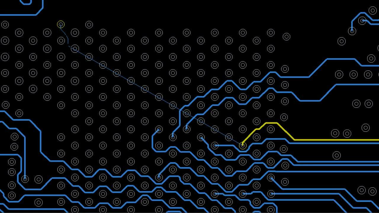
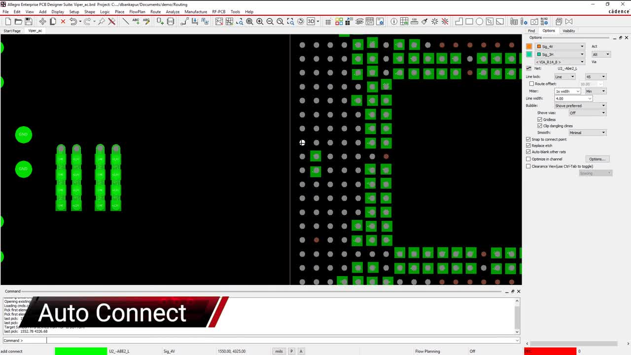
When you are faced with multiple nets that need to be connected, you can use the auto-connect feature in Allegro to relieve you of having to manually route them. By choosing which layers you want to use and then selecting the nets you want to have routed, Allegro’s route engine will complete these routes for you. You can see a demonstration of this capability in the video at the top of this article.
Along with auto-connect, Cadence has provided many other routing features in Allegro to help you to be more productive in the layout of printed circuit boards. These include various routing options and modes, auto-interactive routing functionality, and full batch auto-routers. For more information about routing printed circuit boards, please take a look at our E-book on the subject.
If you’re looking to learn more about how Cadence has the solution for you, talk to us and our team of experts.