Key Takeaways
-
Use a multimeter to test fuses, individual components, and power rails for accurate diagnosis.
-
Look for burn marks, bulging components, and hot spots as indicators of faulty components
-
Employ signal probing, automatic optical inspection, and comparison with a functional board for complex troubleshooting.
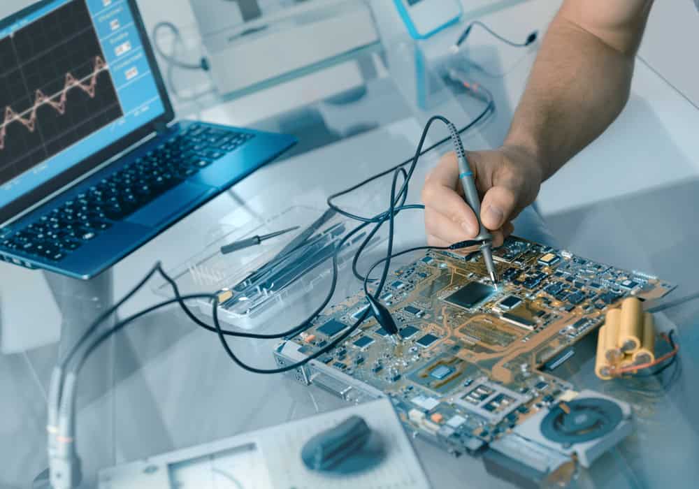
Using an oscilloscope can help detect faulty components.
Troubleshooting circuit boards can be a meticulous process, but following a systematic approach can make it manageable and efficient. Below is a detailed step-by-step guide explaining how to find faulty components on a PCB.
How to Find Faulty Components on a PCB: Manually Step-By-Step
|
Step
|
Instructions
|
|
1
|
|
|
2
|
-
Check the circuit board for fuses.
-
Pull out fuses with long-nose pliers and inspect them.
-
For glass fuses, look at the filament (a broken filament indicates a blown fuse).
-
For ceramic fuses, use a multimeter set to continuity; touch probes to fuse ends (a beep indicates a good fuse).
|
|
3
|
-
Visually inspect the circuit board for obvious problems such as overheated components or bad connections.
-
Look for small brown burn marks indicating overheated components that should be replaced.
-
Check for bulging components or dull-looking connections as indicators of error.
|
|
4
|
-
Inspect physical components with electricity connected to the circuit.
-
Feel different spots on the PCB for hot spots, which indicate faulty connections or physical component issues.
-
Be careful to avoid putting both hands on the live PCB to prevent electric shock.
|
|
5
|
-
Test individual components using a multimeter.
-
Each resistor, capacitor, etc., should register at or below the stated value. Higher values indicate a problem with the component.
|
|
6
|
-
Test integrated circuits by comparing them to a functional IC of the same kind.
-
This comparison is easier than diagnosing individual ICs due to their variability and specialization.
-
Replace individual integrated circuits (ICs) with spares if they are socketed.
-
Test the circuit by plugging the power cord back in and turning the unit on. If the circuit was previously performing poorly or was completely dead and now works fine, the ICs were defective.
|
|
7
|
-
Inspect the power supply by measuring the voltage of the power rails with a multimeter.
-
Expected values should match the component specifications.
-
A 0V reading indicates a short circuit, which causes the component to heat up quickly.
|
|
8
|
-
Compare a defective circuit board with a good one.
-
Visually compare for burn marks or misplaced components.
-
Use a multimeter to compare component values and behavior. Differences likely indicate physical component issues.
|
|
9
|
|
Finding Faulty Components Based on Type
Below, we’ve compiled some common methods of finding faulty components on a PCB based on component type.
|
Component
|
Description
|
|
Electrolytic capacitors
|
-
Start with visual inspection for blown or expanded caps
-
Check continuity with a multimeter: a brief beep followed by rising resistance indicates charging
-
Switch multimeter leads to observe resistance changes
-
Remove from board to measure capacitance if necessary
|
|
Diodes
|
-
Use the multimeter on diode function
-
Negative lead on cathode, positive on anode
-
Measure voltage: 0.1V (Schottky) to 0.7V (rectifier) or 1V (LEDs)
-
Applies to diode bridges ICs too
|
|
BJT Transistors
|
-
Check on board with multimeter's diode function
-
Identify Base pin (varies by package)
-
NPN: positive on Base, negative on collector/emitter; ~0.7V - PNP: reverse polarity for same test
|
|
Coils
|
|
|
Transformers
|
-
Measure resistance similar to coils
-
Identify primary and secondary coils by pad layout
-
Primary coils usually have higher resistance
-
Ensure no open circuits; check for internal fuses if necessary
|
|
Resistors
|
-
Measure resistance on board
-
Lower than expected value may indicate parallel components
-
Visually inspect for damage before measuring
|
|
MOSFETs
|
-
Best to remove for testing
-
Identify pinout - N-channel: negative on Source, touch Gate with positive, then move positive to Drain for short circuit
-
Reverse leads: Source-Drain should measure 0.7V (parasitic diode)
-
Deactivated: Drain-Source open circuit; activated: Drain-Source short circuit
|
|
ICs
|
|
Methods of Finding Faulty Components
Additionally, there are some methods we’ve summarized below that you can use to mass-check multiple PCBs.
|
Method
|
Details
|
|
Visually inspect surface elements
|
-
Detects excessive heat generation
-
Identifies burned-out components, traces, or solder joints
-
Other indicators: bulging/overlapping/missing components, dulled traces, cold joints, excessive solder, tombstoning, lifted/missing pads, cracks
|
|
Using an automatic optical inspection machine
|
-
Automatically scans for defects
-
Captures multiple images for comparison
-
Indicates mismatches as errors
-
Technician analyzes and rectifies issues
-
Uses cameras and image processing software
-
Identifies issues like missing components, incorrect parts, solder bridges, etc.
|
|
Compare with an identical circuit board
|
-
Easier to troubleshoot with identical boards
-
Compare misplacement and defects visually
-
Check input/output readings with a multimeter
|
|
Flying probe testing
|
-
Identifies shorts, open circuits, incorrect parts
-
Detects defects in IC's diode protection
-
Rectifies short circuits and component faults
-
Challenging to resolve open circuits in HDI boards
|
Using OrCAD X to Reduce Faulty Components on Your Board
Using an advanced PCB software like OrCAD X can help create more reliable boards, thus reducing the risk of faulty components on your PCB before they occur. Below we’ve summarized some important OrCAD X features.
|
Tool
|
Description
|
How it Reduces Faulty Components
|
|
Design Rule Checks (DRC)
|
Automated checks validating PCB design against predefined rules.
|
Identifies spacing, clearance, and other design violations in real-time, enabling early correction and reducing manufacturing defects from assembly or solder bridges.
|
|
Constraint Management
|
Allows setting and managing design rules and constraints for PCB elements.
|
Ensures adherence to design and manufacturing requirements, reducing the risk of errors and improving design reliability.
|
|
Live BOM (Bill of Materials)
|
Provides real-time updates and analysis of the bill of materials.
|
Helps select available, compliant, and low-risk components, reducing delays and ensuring reliable component usage.
|
|
Real-Time Assembly Checks
|
Provides real-time feedback on potential assembly issues.
|
Identifies assembly issues during the design phase, allowing adjustments to ensure smooth assembly and reduce faults.
|
|
DFA and DFT Constraints
|
Design for Assembly (DFA) and Design for Test (DFT) constraints.
|
DFA ensures proper component spacing and placement, while DFT ensures adequate testing requirements, reducing assembly and testing errors.
|
Now that you know how to find faulty components on a PCB, to test out these OrCAD X tools firsthand, try out a free trial today. Experience the benefits of advanced PCB design and troubleshooting tools for yourself!