Home
Free Trial
Home
Free Trial
Read More
Content
Filter
10 results found
Featured
Working with Power Supply Design Tools
Featured
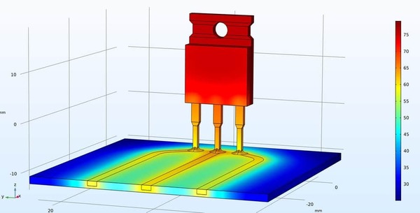
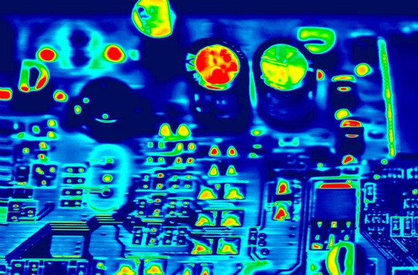
Tips for IC Package Thermal Simulation
Featured
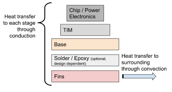
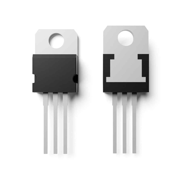
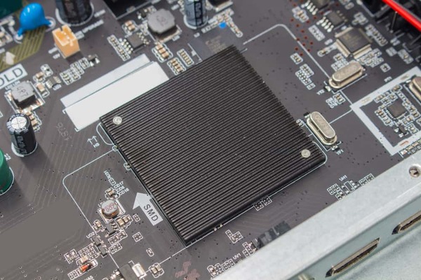
Heat Sink Design for Power Electronics
Featured
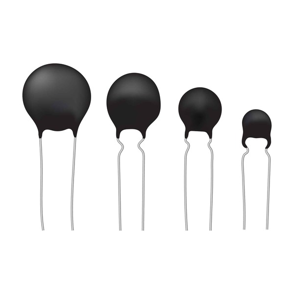
Thermistor: Function and Roles
Featured
PCB Thermal Analysis Tools Improve Reliability
Featured
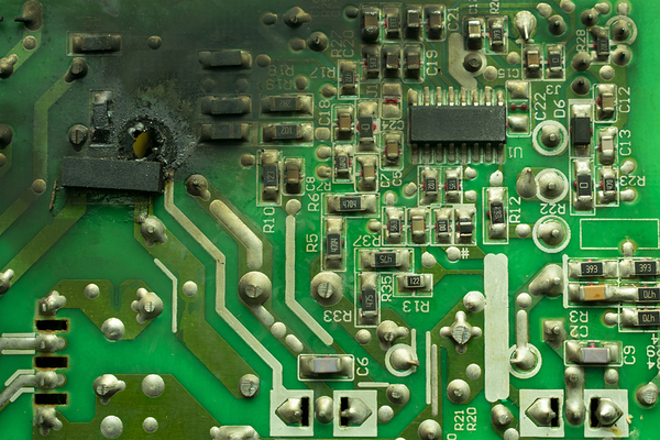
Failure Modes Listings and Their Common Causes
Featured
Does Your Design Need a Heat Sink for SMD Components?
Featured
Embedded Copper Structures for Extreme PCB Thermal Management
Featured
How Packaging Styles Influence the Selection of Heat Sinks for SMD Components
Featured
Overview of Thermal Interface Materials for Electronics
Featured
Products
None
OrCAD X
(2)
Sigrity X Aurora
(1)
Content types
None
Blog
(10)
Solutions
None
Schematic Capture
(1)
Simulation & Analysis
(5)
PCB Layout
(1)
Design for Reliability
(2)