Impedance Matching Between Ground Plane and Power Plane
“Hudson stays grounded amidst Pujols hoopla, leads Cardinals to 4-2 victory.” As you take a break from your current PCB project, think about Hudson. I suppose that Hudson does have a direct physical connection to the earth but I’m not sure if he would like to serve as a common return path for electric current. But…at least the Cardinals won.
In the English language, the phrase “grounded” carries positive and negative meanings. If you are a well-balanced, sensible person, someone may have referred to you as “grounded.” Children and young teens who have broken a rule become grounded—or forbidden to leave the house unless the activity is official. Grounding a pilot prohibits the individual from flying. Manufacturers can ground a fleet of aircraft because of mechanical or electronic problems.
Get to Know Your Ground and Power Planes
Let’s review for a second or two.
Using a ground plane for your PCB design offers the benefits of protecting the circuit from external source radiated EMI. Instead of attempting to route multiple return traces next to all signal traces, you can use a ground plane to minimize EMI susceptibility in your designs. Ground planes additionally help decrease loop inductance in your design by placing the ground return close to the signal line and by routing ground returns from a component through a via to the ground plane.
As with ground planes, power planes consist of a large copper area on the PCB. If your multilayer PCB includes four or more layers, you can assign at least two layers as a ground plane and as a power plane. Typical designs split the power plane into separate domains for different voltage requirements.
What is the Right Path?
When diving into PCB design, establishing return paths becomes a priority. Let’s break the concept of return paths down into smaller bits. A return path is the path that current follows to return to the source. Current returns along the path that offers the lowest impedance. And….the plane located directly below the signal trace is the lowest impedance return path. Finally, the lowest impedance return path also presents the smallest current loop area.
Despite knowing those characteristics, establishing the correct return paths for signals sometimes presents a challenge for PCB design teams. Some of this complexity has occurred because of the need to produce smaller PCB footprints or to use rigid-flex designs. To achieve good signal quality for your design, you should always establish a ground return path in the same layer or an adjacent layer for differential pairs, power planes, and single-ended signals. Maintaining low impedance for all areas of the ground plane for the entire PCB improves power control and signal quality.
Matching impedance between ground and power planes helps your design
Although the ground plane has the most important impedance role, both ground planes and power planes appear as low-impedance paths for signals and can help reduce noise in a circuit. The return signal follows the path of least impedance to the power supply return. As you work with higher frequencies, impedance becomes a much greater factor and—as a result—you must account for reactance, inductance, and capacitance.
Because high frequencies have an impact on circuit behavior, the proximity of a power plane makes a difference for your design. High frequencies increase the skin effect of the circuit and cause currents to flow along the surface of the conductor. As a result, the plane can begin to electrically act as two conductors. Increasing the frequency also allows mutual inductance between the trace on the signal layer and the plane located directly below the trace to increase. In turn, the mutual inductance allows a low-impedance path to develop and allow the return current to follow the trace.
Recognizing the impact of these factors takes us back to a key issue for PCB design and return paths. That is, we want to establish desirable return paths that minimize opportunities for noise and electromagnetic interference (EMI). While you can accomplish this goal through the use of ground return vias and paths for all high frequency signals, understanding how to avoid discontinuity problems can prevent undesirable paths from occurring.
Beware the Path of Discontinuity
Good PCB design recognizes that the behavior of clock signals and other signals that have fast rise/fall times can create problems with EMI. For example, any signal moving over a power plane before reaching the ground plane can become part of a shared electric field that contains noise. This noise can become part of the signal.
When we first considered impedance and signal paths, we determined that the lowest impedance path also has the smallest current loop. Anything in the physical PCB layout—such as a slot in the power or ground plane or a split plane--can introduce discontinuity into the current return path allows a larger current loop to develop. Allowing the current loop size to increase also changes, the impedance, allows the opportunity for noise to radiate from the PCB to occur, and creates a ready-made environment for crosstalk between adjacent traces and distorted waveforms.
Stay Focused While on the Tightrope
The concept of providing the lowest impedance return path seems straightforward. However, complex designs that feature high frequencies also demand more from the power supply. Without a stable power supply, the constant switching of numerous components can cause transient currents. If the power supply impedance increases, a large voltage drop can occur and cause instability. In addition, increasing the frequency causes the impedance to rise. Because of this phenomena, PCB design teams must take steps to decrease the power supply impedance as much as possible.
SMD components can affect your plane performance
At this point, we need to reconsider the ground and power planes as a large plate capacitor. All the ingredients for capacitance exist with a parallel area between the ground and power planes, the dielectric constant of the board material, and the distance between the planes. We can calculate the characteristic impedance (ZO) that exists between the two large planes by considering the dielectric constant (r), the distance between the planes (h) and the width of the planes (w).
To maintain a lower power supply impedance, desirable return paths and achieve a matched impedance between the ground plane and power plane and to maintain desirable return paths, we can use decoupling capacitors to decouple the power system.
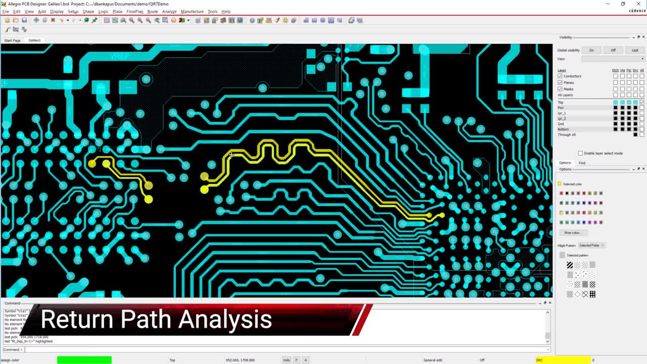
Cadence is a host of strong layout, design, and analysis tools capable of working through the necessities that your board may present for impedance matching. With Allegro’s PCB Editor you’ll be rest assured with one of the strongest design tools available.
If you’re looking to learn more about how Cadence has the solution for you, talk to us and our team of experts.