Keys to Success with Your PCB CAD Parts Library
From ancient Alexandria to the roll-away cart in a small kindergarten class, libraries have long held the position of being a trusted source of knowledge and entertainment. Whether through books or electronic documents, we’ve relied on libraries to reveal the wonders of the world to us and provide us with reliable information. It only makes sense then that with the need to store important part information for CAD systems, that this data would be organized into “libraries.”
PCB design CAD systems have long used a library style system of containment for their component information. Not only has this provided a useful method of organizing the different types of CAD data, but given designers a great deal of flexibility to create multiple libraries for different purposes. Let’s take a look at how a CAD parts library is essential for your work as a PCB designer, how to get the most use out of it, and what the future has in store for libraries.
You Won’t be Designing Your Board Without a Trip to the CAD Parts Library
Schematic capture and PCB layout CAD systems rely on a collection of parts or models with which to operate. These models are kept in a file system that has traditionally been referred to as a library. The models represent different elements required for the use of PCB design systems including the following:
-
Symbols: The different logic symbols that you see on a schematic, such as resistors, capacitors, and integrated circuits, are all represented by library parts.
-
Footprints: Each component footprint pattern on a printed circuit board is modeled by a library part. In some cases, these footprints may include additional embedded library parts as well.
-
Drawings: These library parts can be everything from a full set of manufacturing drawings, to a simple schematic sheet border.
-
STEP models: These parts are what render a physical component in 3D.
These are the basic library parts that you will find, but depending on the CAD system that you are using you may find others that are not here on the list. It all depends on how that particular CAD system is designed to operate.
When placing one of these parts or models on a schematic or a layout, a copy, or instance, of a library part is used in the actual design. As you can guess, this could cause some grief if those library parts get changed unexpectedly, and no longer match what is in the design. For this reason, there are many safeguards in place to make sure that this doesn’t happen. One of those safeguards is a set of CAD tool features that check for inconsistencies between library parts and parts used in the design. Library parts will need to be updated for part changes or corrections, and the best tools will give you features to check for those changes and automatically update the parts in the design.
3D footprint models in a PCB layout
More than Just Components, What Else Can Your Library be Used For?
Earlier we mentioned the various library elements that PCB Design CAD tools will use including symbols, footprints, and drawings. There are other ways to use a library with your CAD system however, that aren’t necessarily required for tool operation like a symbol is. Many companies will employ the use of libraries to collect and manage design resources like the following:
-
Designs: As the amount of your designs grows over time, they can become difficult to manage. One practice that can help is to develop a library type system to store your different designs. These can be categorized by projects, technologies, or any other criteria that would be important to your organization.
-
Templates: It is often useful for a designer to have access to templates or examples to either use or learn from. Although the PCB design CAD tools usually have templates within them for drawing formats and other basic elements, they won’t necessarily have templates that are customized for your specific company’s needs. Creating a template library can help your designers so that they don’t have to recreate the same drawing outlines over and over again.
-
Drawing elements: Keeping a copy of the different views, details, and notes that your company uses can be another useful productivity enhancer. In addition to saving time, using saved drawing elements can also help to reduce common errors that can occur by recreating the same elements manually for each new design.
These are some of the more common examples of libraries that designers have used to augment their CAD systems. Our advice would be that any element in your designs that you find yourself recreating over and over again, is probably a good candidate for storage in a library.
We’ve shown you so far what libraries are and how they can be used, but as with any type of technology, there are now new ways to use CAD libraries in your designs.
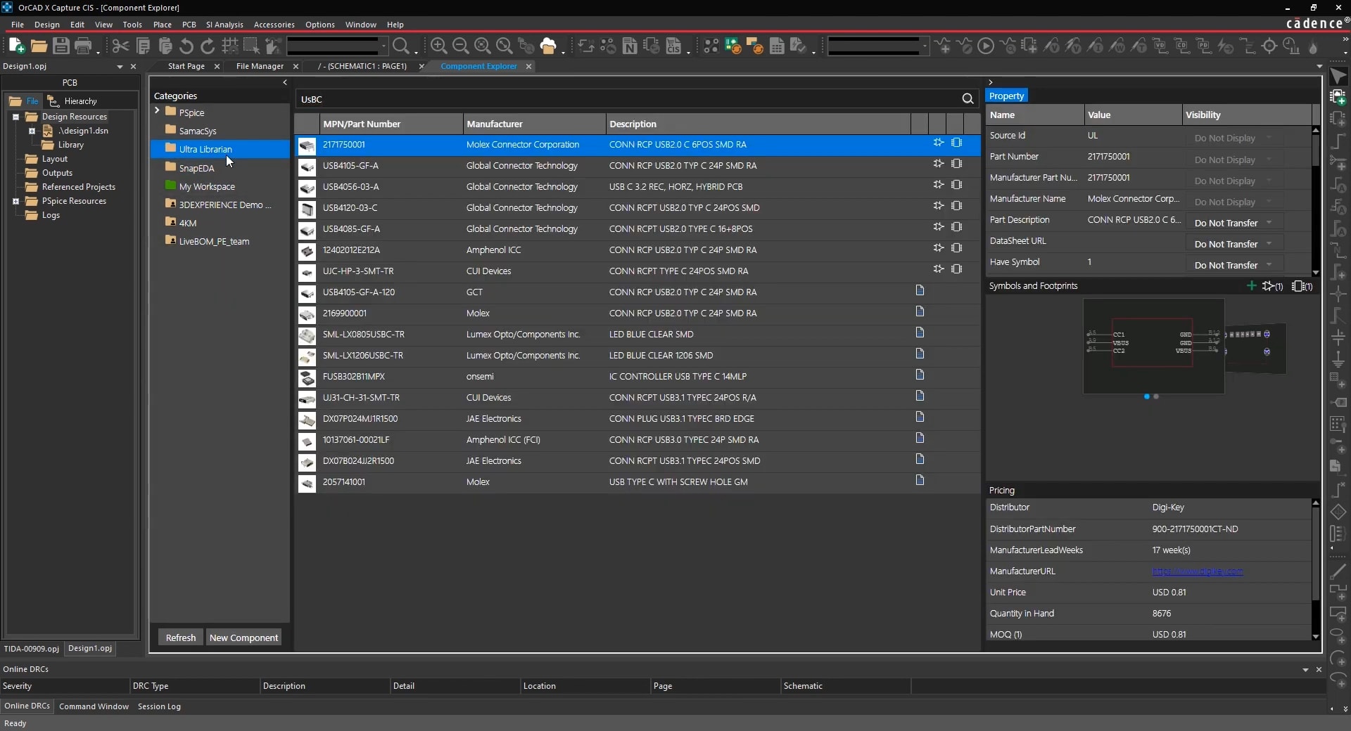
The New CAD Parts Libraries; Online Part Providers
More and more PCB design CAD systems are incorporating online libraries within their tools. These systems employ a menu that connects with an online part provider, giving the user a catalog from which to pull parts from. Often there are multiple services that the designer can use, and they will be able to filter the menu in order to refine their search, such as searching only for resistors. The tools will report the manufacturer’s name and part number of the device chosen, and provide the ability to view datasheets, download symbols, footprints, and 3D models into the design if they are available.
Using these systems helps guarantee the accuracy of the parts since the information comes directly from the part manufacturers or suppliers. Designers can trust that the footprints will be built correctly to industry standards and that these parts are optimized for the system that they are using.
A good example of a PCB design system that has the library features that we have been talking about is from the advanced EDA tools created by Cadence. OrCAD PCB Designer has the library functionality that we’ve been talking about built into its systems. Using these tools you can easily work with schematic symbols and PCB footprints, plus many other library elements as well. Additionally, OrCAD now comes with a Unified Parts Search feature. This will give you access to thousands of parts online that you can quickly find and incorporate into your design without leaving your design environment.
If you’re looking to learn more about how Cadence has the solution for you, talk to us and our team of experts.