07 - Managing Shapes in OrCAD X Presto
OrCAD X Presto offers effective shape management capabilities to create layout designs that are both functional and manufacturable.
Creating and Adding Shapes in OrCAD X Presto
Regardless of whether you are in working on footprint or board files, basic functionality is as follows when creating and adding shapes in OrCAD X Presto.
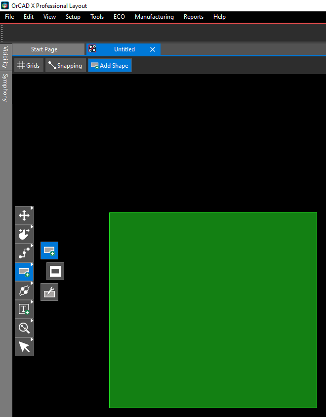
Choose the Add Shape icon from the toolbar. ![]()
Choose the shape ( Polygon, Rectangle, Circle) you would like to draw, as shown in the following Add Shape dialog.
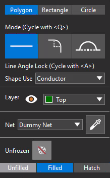
The Polygon tab, following, lets you draw polygons with three different options:
- Straight line
- Tangent arc, with curved edges
- Perpendicular arc, with semicircles
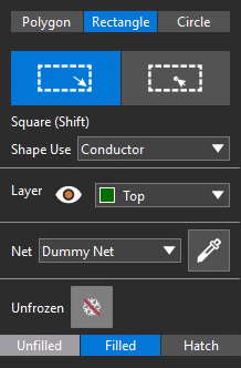
The Rectangle tab, following, lets you draw rectangles with two different options:
- Corner to Corner
- Center to Corner
The Circle tab, following, lets you draw circles with two different options:
- Radius
- Diameter
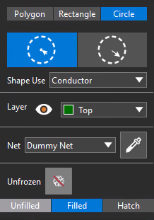
For all shapes (polygon, rectangle, or circle), you have the following Shape Use options available from the drop-down list: 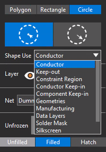
Drawing Rectangles and Circles
Drawing circles and basic rectangles is fairly straightforward.
Click and hold the left mouse button to begin drawing the selected shape. The point at which the cursor is placed when you first click the mouse button will become a corner of your rectangle, or a point on the edge of circle, respectively.
As you move the cursor with the mouse button depressed, the shape will get larger or smaller, according to your movements. Let go of the mouse button to finalize the size of your shape.
Drawing Polygons
Choose the Add Shape icon ![]() from the toolbar. Then choose Polygon from the Add Shape dialog, as follows:
from the toolbar. Then choose Polygon from the Add Shape dialog, as follows: 
Set your parameters for Shape Use, Layer, Net, and Frozen/Unfrozen in the Add Shape dialog.
Click on points to add segments and construct a closed polygon, keeping in mind that the tool will close your polygon when you click on your starting point only if the defined shape is legal, based on the shape creation parameters you set in the Add Shape dialog.
Additionally, you can choose the Net, and designate shapes to be either frozen or unfrozen, as shown in the figures above.
Your can add three different types of segments—lines (default), tangential arcs, and perpendicular arcs—from one mouse click point to the next point you click.
Choose the appropriate icon for whichever segment type you want or by sequencing through the segment type choices using a hot-key (default is Q). 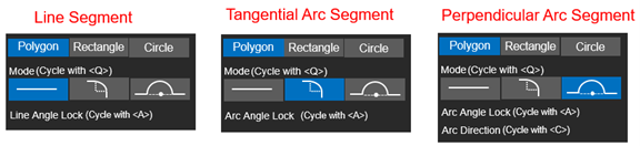
When you set the segment type to Perpendicular Arc Segment, the Arc Direction setting dictates in which direction (clockwise or counter-clockwise) the arc is drawn. The angle direction can be changed only with a programmable hot key (by default, C).
The tool always begins drawing the perpendicular arc in Auto mode. You can take temporary control of the exact direction with the hot key, if needed, but this direction control (which toggles between clockwise and counter-clockwise) will last for only the addition of that proposed perpendicular arc segment.
Updating, Freezing, and Un-Freezing Shapes in OrCAD X Presto
You can update, freeze, or un-freeze shapes in OrCAD X using the Properties panel. Ensure that Shapes are being shown (as seen below in blue), and expand the General tab. You can choose a shape from your design and toggle between Frozen (as shown immediately below, in blue) and Unfrozen. 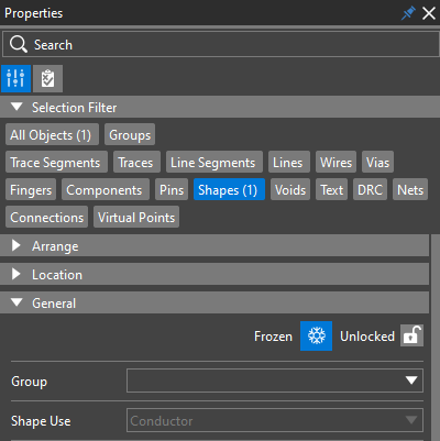
If the shape is not up to date, Out of Date is shown in red, as follows: 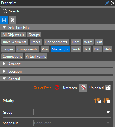
To update, click the red refresh icon ![]() , and Up to Date will appear in green, as follows:
, and Up to Date will appear in green, as follows:
Shapes that are not frozen can be edited and the fill is deferred until all edits are finished, so it happens only once. With frozen shapes, fills are updated instantaneously, in real time. You cannot set parameters of frozen shapes.
You can also lock ![]() or unlock
or unlock ![]() shapes as necessary.
shapes as necessary.
Editing Shape Edges in OrCAD X Presto
Sometimes, it is easier to create the rough polygon of a shape with corners and then apply trimming to achieve desired chamfers or rounded arcs. In OrCAD X Presto, you can choose entire existing shapes or individual corners of those shapes, and trim them into either rounded arcs or chamfers.
To trim corners, first open the Shape Utilities dialog, as follows:
- Right-click over the Add Shape icon in the toolbar. Additional icons will appear, as shown below.
- Click the bottom-most icon for Shape Utilities.
To edit corners of a shape individually:- In the Shape Utilities menu, choose Trim Corners.
- Toggle OFF Trim Entire Shape.
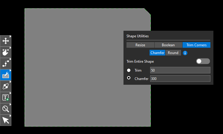
- Choose either Chamfer or Round.
- Set the desired chamfer or radius value.
- Click on the corner of the shape you are trimming.
Editing Shape Edges Dynamically
OrCAD X lets you dynamically access and change shape editing options to see the proposed impact of your edits before actually committing them to your design. For example, you can auto-join (that is, Remove Vertices) and extend selections (that is, Preserve Corners), and toggle between the two with a programmable hot-key (default is the T key) to see the difference before actually making the change.
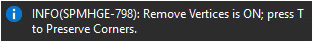
- Choose a shape you want to edit. Once it is selected, you can left-click to drag-select an edge or vertex to edit. At the top-right of the tool, you will see the following dialog box:
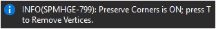
- You can then switch between Remove Vertices and Preserve Corners using the hot-key to visualize the impact of the edit on the dynamics of your design.
- If you click T, the dialog box will toggle to the following:
- You can toggle between the two and adjust edges until you are satisfied.
- Once you achieve the result you want, you commit the edit by releasing your mouse click/drag.
View the next document: 08 - Creating Zones and Bends for Rigid-Flex Design in OrCAD X Presto
If you have any questions or comments about the OrCAD X platform, click on the link below.
Contact Us