Notes on Near Field Communications
Notes on Near Field Communications
NFC is a touch-and-go standard for sharing a few packets of data with another device that is in close proximity. How close? Centimeters. The small broadcast and receive areas help thwart data theft and keep system noise to a minimum. This gives NFC enabled devices robustness that will allow them to be a little lower on the list of priority nets. You would typically be more concerned with other radios and high-speed connections. If this is all you need to reach the outside world, then you should be in good shape.
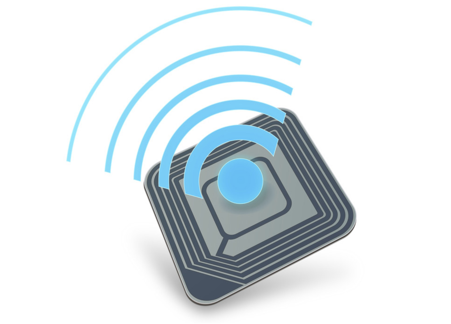
Image credit: projekt-pionier
Shielding over the device is a worthwhile idea. We have been able to do without actually installing the shield on the PCB. The presence of the footprint for the shield walls was sufficient for isolation. I cannot speak for every application when saying that we passed the FCC certification without the shield. Every design will be different. This infographic shows some of the many ways NFC is implemented. It also predicts that 2.2 billion devices will be equipped with the technology by 2020.
Here is one sentence from the NFC Forum describing their approach to the standards.
By utilizing the key elements in existing and recognized standards like ISO/IEC 18092 and ISO/IEC 14443-2,3,4, as well as JIS X6319-4, the NFC Forum Specifications form a technology standard that harmonizes and extends existing contactless standards unlocking the full capabilities of NFC technology across the different contactless operating modes, peer-to-peer mode, reader/writer mode, card emulation mode.
That is a rambling statement among many others. The goal here is to distill that kind of language into simple English or, at least, something a PCB Designer would be willing to read. Let’s dive right in.
NFC-V is the latest iteration. Like other protocols, a few iterations have come along since the introduction in 2002. The improvements are generally about increasing the number of ways to connect. The three headers at the top of the chart below describe the main use cases.
-
Peer to Peer mode is the one where photos and other files are exchanged between active devices.
-
The reader/writer mode is the internet of things approach. The possibilities are basically limitless. One thing comes into proximity to another and something happens.
-
Card Emulation Mode opens doors and does other smart card functions. Each of these modes enables a variety of tasks.
The beauty is that there may still be a killer app out there that nobody has thought of yet. Dream it up. Make it happen and take your device to the next plugfest to see if it interoperates with all of the others.
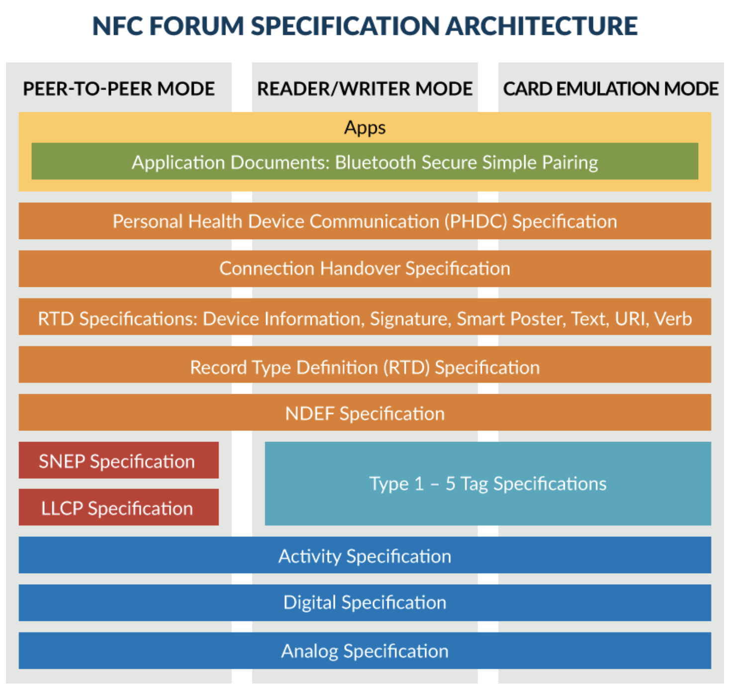
Image credit: NFC forum
The parent technology of NFC is RFID. The cool thing about RFID is that power is only required for one side of the link. A completely passive device is energized in the presence of the reading device. RFID tags do not need a battery or a mains connection to be able to tell their story. The composition of such a device is a coil for capturing the transmitted power inductively and a small memory chip to store/retrieve data. There are numerous flavors of these tags. Not all RFID tags are writable nor are they all passive.
Package delivery companies, for instance, will tag the package which stays with the end customer when all is said and done. It’s a one-way trip and the data (essentially an invisible QR code) doesn’t change over the course of the trip. Tracking the packages all the way to the door helps the shipper monitor their logistics and helps the customer anticipate deliveries. That would require a read-only tag.
The mechanism for NFC is like that but instead of a tag and a reader, both ends of the link can operate either way. They take turns going from passive to active mode, but not much data actually passes over the link. NFC is more likely to initiate a Bluetooth or WiFi connection where the actual business cards (or whatever) change hands. NFC is like a door to a room where very specific information is stored. Imagine a reloadable gift card. The NFC protocol is not concerned with how much money is on the account, only that you can get in.
The Obligatory Math
Thus, the bitrate will be rather low. The NFC Forum Technical Specification allows three speeds. They are 106kbps, 212kbps, and 424kbps, below megabyte and well short of gigabyte data rates. In terms of wireless frequencies, NFC uses the high frequency (HF) version at 13.56 MHz. For reference, RFID uses three different versions; low frequency runs from 125 to 134 KHz and at the other end of the scale, ultra high frequency at 433 and 860 to 960 MHz. NFC is bound to the one channel where RFID is spread across the spectrum. Routing a 13 MHz line (or 2 pairs) requires the usual care afforded to controlled impedance traces.

Image credit: TME Electronic
The matching network is fun. There is a little more to it than a pi pad. You just have to cobble the pieces together such that the TX and RX have the prettiest paths and you should be fine. As you can see, the antenna is the space hog. There would be no components on the surface and no routing on other layers under the antenna.
Looking at the edge of the board, you can see that it is darker where the components are. It’s actually thinner and a lot more bendable where the antenna goes when you try this with a high layer count. Not a two-layer problem; I confess to a really floppy corner on a 12 layer effort.
A board made of nothing but resin and glass with no copper is generally a bad idea. That is the nature of printed antennae. Bless our RF experts for using physics to connect the world. The price is the creativity required by the fabricator to pull off all these amazing stunts. Passive NFC beacons are being made of metalized paper and a memory chip.
The PCB industry is tasked with keeping up with progress from the chip world as a whole. It just seems like the analog team is the one that really has to push the envelope. It turns out that you can have “everything” so that’s what we want.
Parts is Parts
From a chip supply point of view, NXP is the co-inventor (along with Sony) and the leading provider of the devices. Yes, my old company, Qualcomm and their rivals Broadcom also make them but mainly as multifunctional devices that include Bluetooth and/or WiFi. I don’t remember seeing a pure NFC chip from either of those players. This is NXP’s Sandbox. Sony, Samsung, Intel, and the usual suspects are also in the game to some degree.
The devices are generally small BGAs or QFN packages that require a little finesse to fan-out. Pin pitch is normally 0.5 mm. In addition to the radio, the bill of material will include a number of passive components to form a matching network for the antenna. Of course, there are a few bypass caps and, usually, an external oscillator. Power consumption is low and usage is infrequent in most cases.
A “Million” Uses
The fact that NFC whispers rather than shouts its signal means that the location of the antenna should be identified on the outside of the products. That way, people can align their devices over the target to get the data moving on the first try. You don’t want people “holding it wrong” (too soon?)
With all of the different ways to use an NFC link, it is reasonable to believe that it will happen on one of your boards some day. Other than antenna design, this is a fairly straightforward layout process; though you should be handy with HDI stack-ups and accompanying routing solutions. Whether it is a point of sale, a locked box or some kind of virtual treasure hunt, lots of cool things can happen with Near Field Communications.