DC vs AC Current Design
Key Takeaways
-
Find out the fundamental differences between DC and AC current.
-
Learn how some components behave differently with DC and AC current.
-
Explore the challenges in DC and AC design.
Is the grass always greener on the other side? I spent my late 20s leading a thrilling life of entrepreneurship; each day was fueled with hundreds of decisions that could send me on an emotional roller coaster. Being a parent has also drastically changed my lifestyle. Today, my routine is pretty much the same every day and I have realized that “monotonous” isn’t necessarily bad.
In electronics, I’m also personally biased when it comes to DC vs AC current design. While AC (alternating current) seems exciting to work with, I’m more comfortable with working on DC (direct current) circuits. However, I couldn’t pick my projects as I wished, which means I had to be relatively comfortable working with both types of designs. Let’s take a look at these two styles of circuit design and some considerations for each.
DC vs AC Current
You ought to be familiar with the mechanism of DC and AC, but here’s a refresher:
DC vs AC current on a chart.
DC flows from the permanently fixed positive terminal to the negative terminal of a power source. Examples of this are seen in batteries, USB, and in the current coming out of a charging adaptor. On a chart, DC is represented by a flat, horizontal line.
Meanwhile, AC is the result of the gradual switching of the positive and negative terminals of the power source. As the terminals change state, the flow of the current diminishes and reverses direction. The AC is reflected by a sinusoidal wave on the chart. Both DC and AC play an important role in shaping electrical and electronic systems, albeit in different manners. DC is usually found in low-voltage electronic products that typically involve semiconductor components.
AC is commonly used in high-power transmission systems. For example, a transmission grid and the power socket in your home will have AC flowing through them. Using AC for transmission is more economical than DC. With a transformer, the AC voltage can be raised multiple times while the current is greatly decreased to minimize power loss.
How Components Behave Differently in DC and AC Circuits
Inductors and capacitors behave differently in DC and AC circuits.
It’s a mistake to approach AC circuit design just as you’ve done for DC and vice versa. Some components show different characteristics when AC and DC pass through them. An inductor, which behaves as a short circuit in a DC circuit, resists current flow in an AC circuit.
Capacitors, which are treated as open circuits in a DC circuit, allows AC to flow through. The changes in these behaviors for capacitors and inductors as AC flows through introduces new variables in circuit analysis.
If a circuit purely consists of DC flow, you’ll only need to take resistance into account. However, the presence of AC means calculations must include the impedance contributed by the inductors and capacitors in the circuit. These components could also change the phasor difference between the voltage and current in an AC circuit. For an inductor, the current lags voltage by 90 degrees and vice versa for a capacitor.
Challenges in DC vs AC Current Designs
Safety is crucial for high power AC designs.
Both types of current present their own set of challenges. Just because I’m more comfortable dealing with DC doesn’t mean it’s easier than AC. DC is often generated in low-voltage circuits, such as a motherboard, smartwatch, or drone-controller.
While DC has a simpler formula, there are still challenges that can impact the design. You’ll need to be concerned about problems like heat points, EMI, and return path for DC. When a few traces carrying DC converge, the conductor needs to be large enough to handle the current. As designers working on DC are accustomed to ‘low-power’ design, it’s easy to overlook the trace width required to accommodate the current on the PCB.
The return path is also an important factor in DC design. You’ll need to visualize how current flows and returns from components to prevent coupling of noise into sensitive circuits.
As AC is more prevalent in high-power design and application, safety is a main priority. In an AC circuit, you’ll want to be familiar with what the Live (L), Neutral (N), and Earth(E) does. These terminals should never be shorted, whether intentionally or not. Human contact with L can be lethal and sometimes also with an improperly configured N terminal.
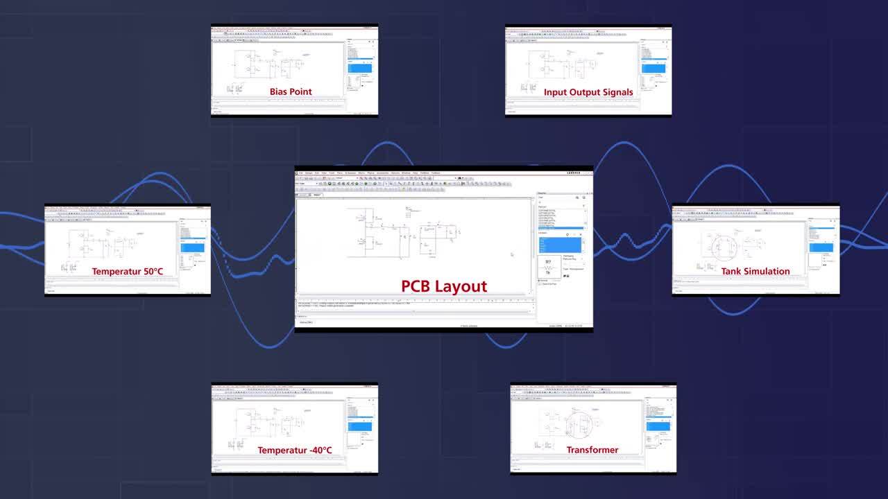
Using a PCB design and analysis software that’s adept for both AC and DC designs can take a lot of the stress off of your shoulders and help you create successful designs with less effort. PSpice Simulator by Cadence allows you to simulate everything you need in your current necessities.
If you’re looking to learn more about how Cadence has the solution for you, talk to us and our team of experts.