08 - Creating Zones and Bends for Rigid-Flex Design in OrCAD X Presto
You can create both zones and bends from the Setup – Flex menu, as follows. 
When creating a zone, the draw shape utility enables you to seamlessly switch between line, arc, and tangent arc, while showing length and angle. 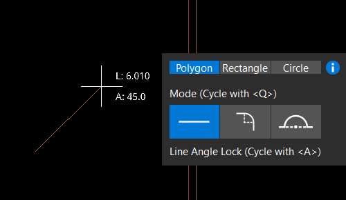
Once you draw a zone or a bend line, its properties appear in the Properties panel. 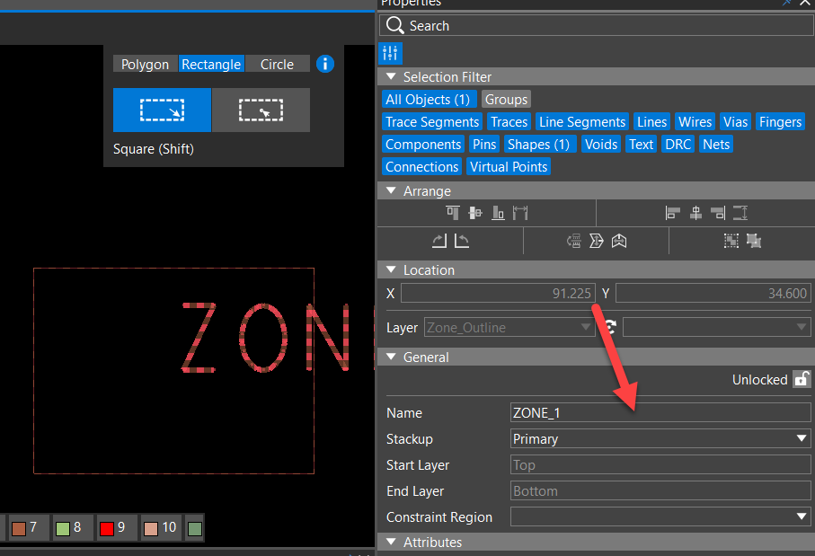
You can choose the design outline to see links showing the number of zones and bends. 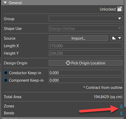
Clicking the blue Zones and Bends links gives you the list of all in the search table, from which you can navigate and change properties of any zone or bend. 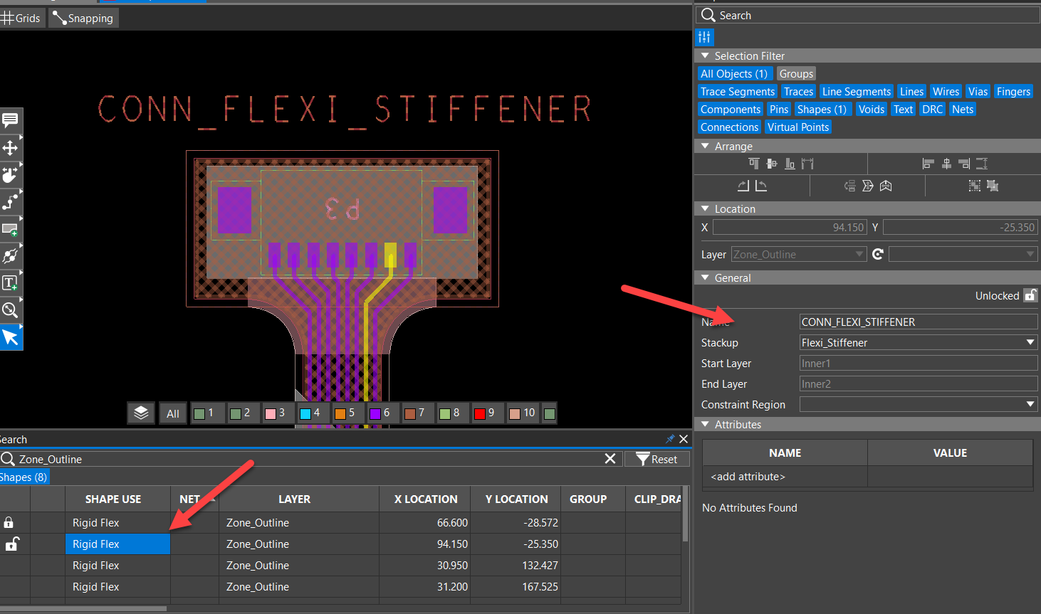
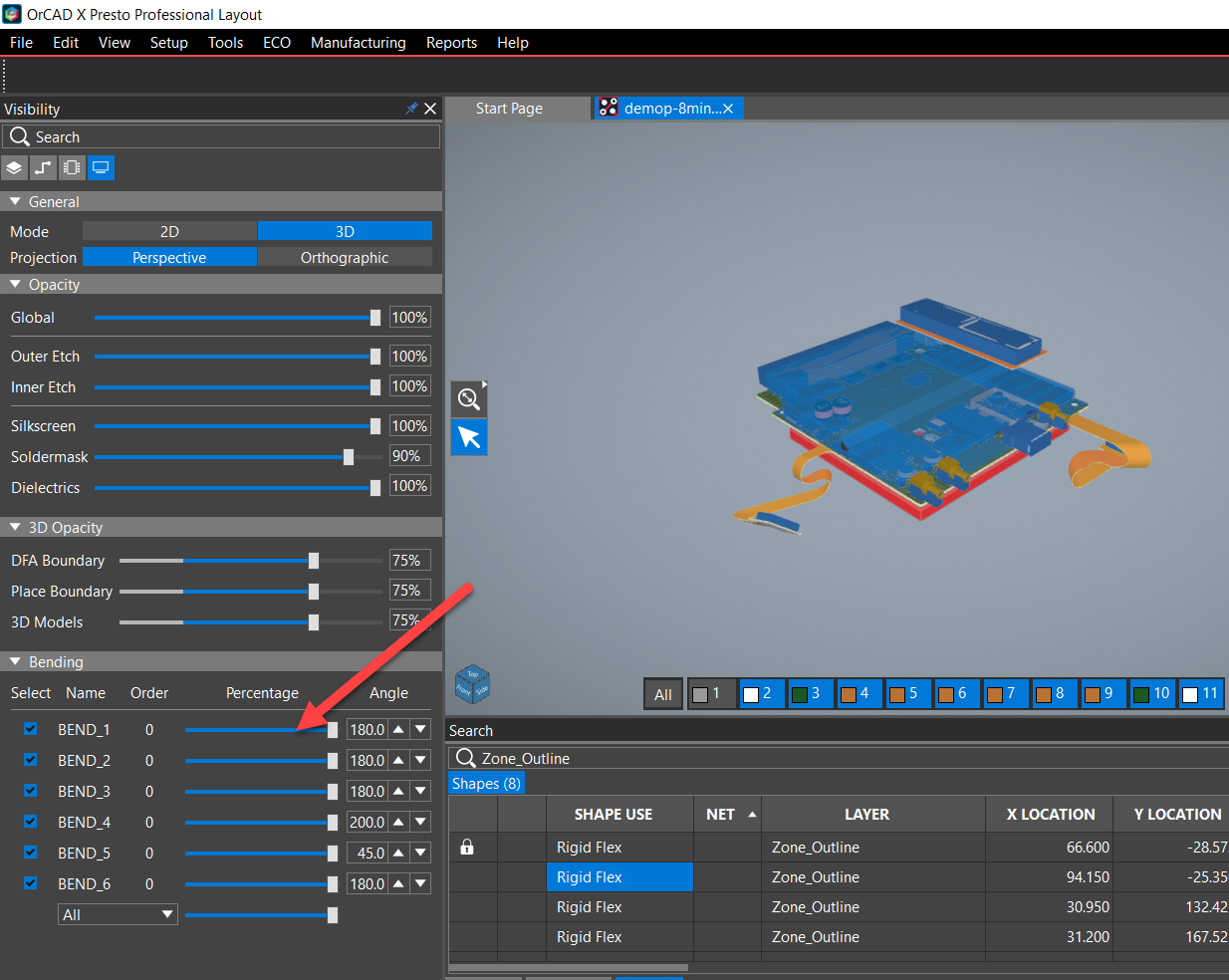
You can access and control visibility of flex data in the Visibility panel, as follows. 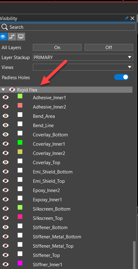
Adding Zone Stackups in OrCAD X Presto
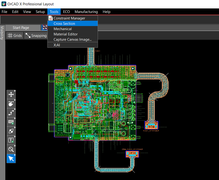
- To launch the Cross-Section Editor, choose Tools – Cross Section from the top menu, as follows:
 The Cross-Section Editor window opens.
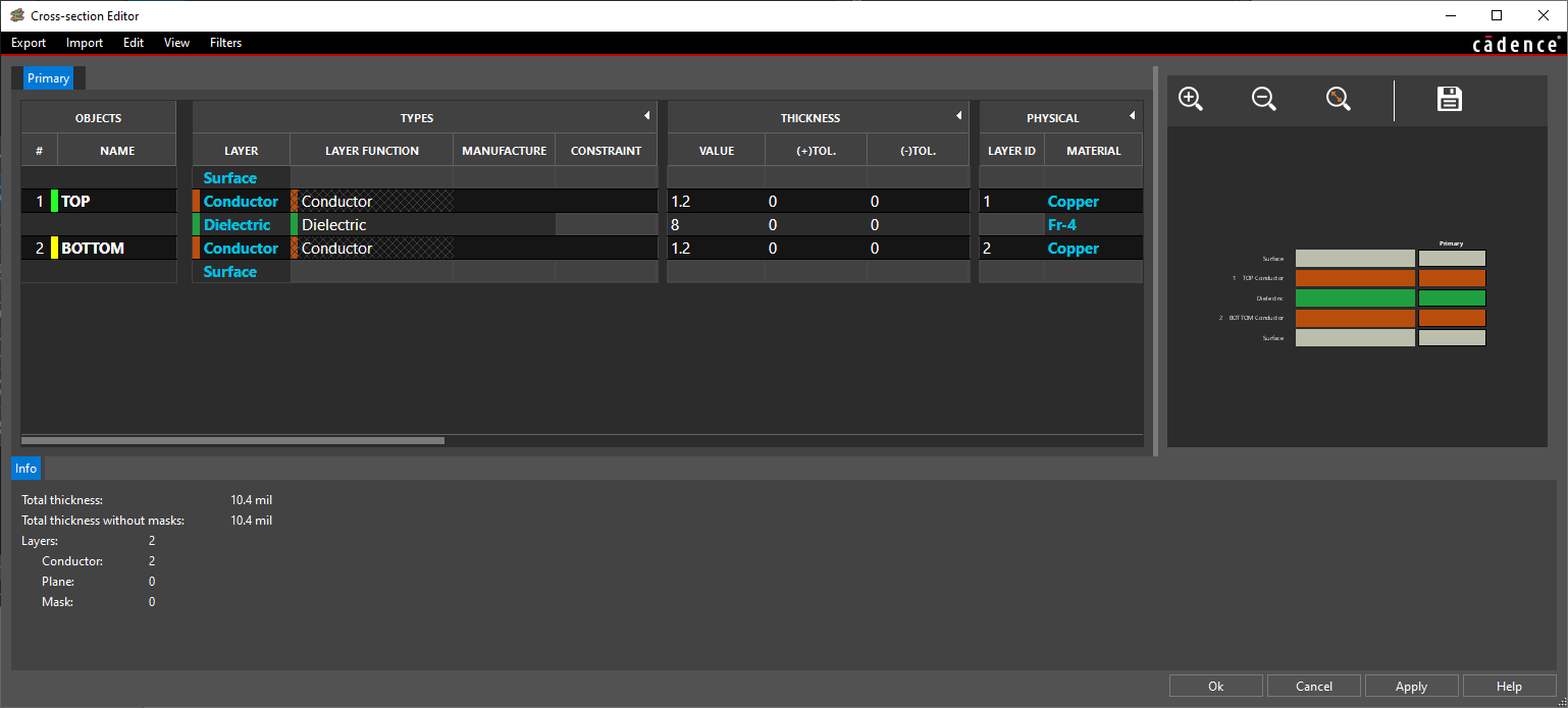
- Choose View – Multi Stackups mode, then Edit – Add Stackup.
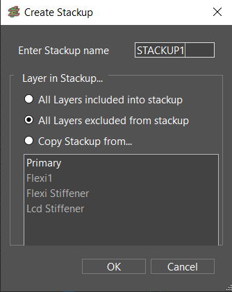 The Create Stackup window opens. For each stack up tab, the cross-section table contains the following data—Objects, Types, Thickness, Physical, Embedded, and Signal Integrity—as follows:
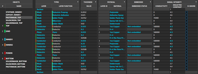
You can expand any column to view all sub-columns by double-clicking the column heading.
Creating and Editing Bends in OrCAD X Presto
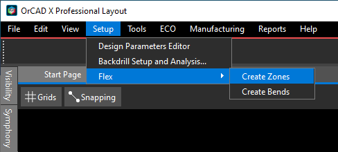
To create bends, from the top menu, choose Setup – Flex – Create Bends, as follows: 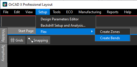
You can start drawing a line segment to specify the bend line.
After creating a bend, its shape in the Rigid Flex/Bend Area layer is selected and the General properties pane looks similar to the following. 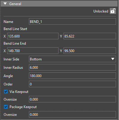
By default, bends are created with the BEND_ <number> naming convention, beginning with BEND_1, but you can rename as you like.
Additionally, bends are unlocked by default, but you can manually unlock or lock them at any time.
You can choose a bend by its bend area shape, bend line, or keepouts. You can edit only the bend properties and not the object properties from the property pane, as follows. When you edit the select-
ed bend, if any of the new values makes it invalid, then the attributes reverts to the previous valid values. 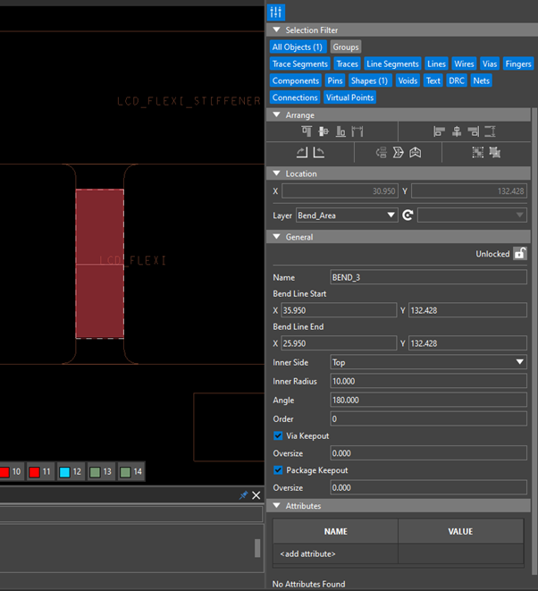
You can delete a bend by choosing its bend area or bend line, and either pressing the delete key or right-clicking and choosing the Delete option. When a bend is deleted, all of its associated objects including bend line, bend area, and keepouts are deleted as well.
The 3D canvas supports bending as well.
Creating and Editing Zones in OrCAD X Presto
To create zones, from the top menu, choose Setup – Flex – Create Zones, as follows:
The tool opens the Create Zones dialog box, from which you can create polygonal, rectangular, or circular zones, based on your selection: 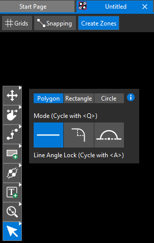
When the zone is created, its boundary shape is selected and the General properties pane looks similar to the following. 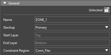
By default, zones are created with the zone_ <number> naming convention, beginning with zone_1, but you can rename as you like.
Additionally, zones are unlocked by default, but you can manually unlock or lock them at any time.
When you choose a zone using its boundary shape, constraint region, or keepouts, the property pane shows its info and is unlocked by default, as follows. You cannot edit or delete the zone outline, constraint region, and keepouts. The constraint region and keepouts are generated automatically when selected from the dropdown in the Properties pane. 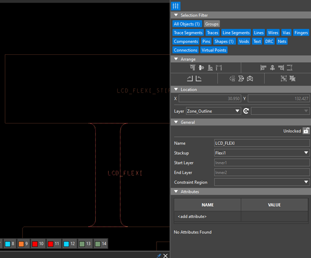
You can delete a zone by choosing its boundary shape, unlocking the zone if it is already locked, and then pressing the delete key or right-clicking and choosing the Delete option, which deletes the entire zone, including the outline, constraint region, and keepout shapes.
View the next document: 09 - Placing Components and Circuits in OrCAD X Presto
If you have any questions or comments about the OrCAD X platform, click on the link below.
Contact Us