PCB Design as Related to Defense Contractors
The Department of Defense is one of the biggest technology customers in the world. Landing a contract can make a company. It can also be a yoke around their neck if they’re not prepared to create documentation in just the right way. There is some latitude in the use of the DOD-STD-100 STANDARD PRACTICE FOR ENGINEERING DRAWINGS but not as much as we’ve come to expect in the non-DoD world.
Standards - There is a Standard for Literally Everything
The DoD 100 standard is a document of documents. It incorporates many other documents by reference. A short list of standards bodies that fall under their aegis include (naturally) MIL-STDs and MIL-HDBKs (hand books) but also selected works from the ASME, ANSI, IEEE and our favorite, the IPC.
Every one of those organizations has umbrella documents that then refer to more individual documents that specify the details. By the time you’ve seen the entire catalog of referenced specifications and standards, you’ve pretty much seen the entire Library of Congress; or so it seems. The title block of your drawing probably has a box for the CAGE code. Thank Uncle Sam for that one.
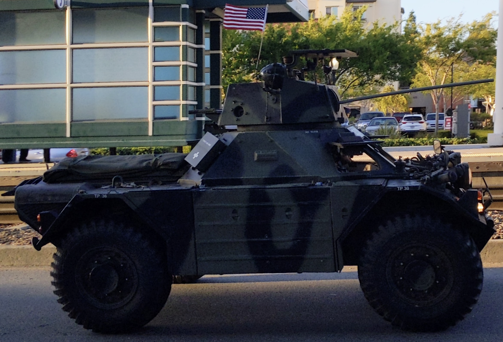
Images Credit: Author - A drive-by in a mystery machine, I think it’s called a Ferret.
There’s good news. A book called the Drawing Requirements Manual (DRM) consolidates this information down to about 1000 pages over 26 chapters. I soaked myself in those pages during my PCB design and ECAD training. When I got in with a subcontractor, a Mechanical Engineer asked me if I had a photographic memory. No, I have a priority to know what is expected on the job and to be able to exit the trade school with valuable skills. Those skills are found in every chapter of the DRM.
The slash sheets we’re used to in IPC-4101 and IPC-4103 can be used as a reference. The material note SHALL include the relevant parameters in detail. “SHALL”? Get used to some words being capitalized as a matter of course. When using all caps, the imperative words may be bolded and/or underlined for emphasis. The Government uses words from “Olde English” to let you know when they are serious. They’re always serious.
Text Sizes SHALL Conform to Minimum Requirements for Archival Purposes
There is a specification for text height. The minimum size on an A, B, or C size drawing is only 3.175 mm while D size and above will require 3.556 mm minimum. The space between lines SHALL be at least half the text height. Yes, the auditor will have calipers handy to check your blueprints for any fine print. While we can scale up a .pdf file and read the smallest text, the DoD is fond of using microfilm as a back-up copy.
Naming Conventions - Enough to Distinguish a Product and Not One Word More
Naming conventions are even more ridiculous. The order of the words in the description field is tightly controlled and goes from the general description down to the details. Many words are considered too ambiguous to be used. Compound words should be kept in order but it’s not always clear what fits that designation. Cataloging Handbook H6 Federal Item Name Directory for Supply Cataloging is where you would find the approved words. Abbreviations or acronyms are forbidden in the first part of the description but common ones MAY be used in the second line.
I don’t know anything about HoloLens or its use in any Military programs. And, if I was aware of any such program, I would not be at liberty to discuss any such program. You get my gist? I can tell you that my favorite program was called WRTTM FTT HPA. That stands for Warhead Replaceable Tactical Telemetry Module - Flight Termination Transponder - High Power Amplifier. That component replaced the explosives in the nose cone of an AMRAAM, or the Advanced Medium Range Air-To-Air Missile that went under the wings of the ATF.
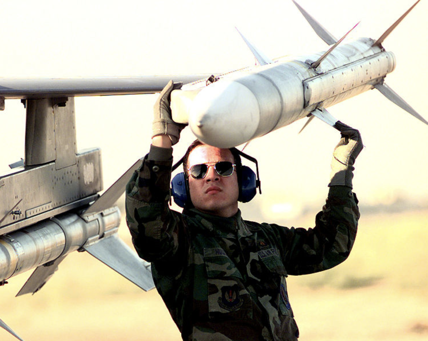
Image Credit: USAF - The lovable AMRAAM
The Advanced Tactical Fighter, now known as the F22, is considered the best pure fighter jet ever. Thirty years ago, mentioning that name outside of the silo would have gotten me under some seriously bright lights, if you get my gist. A one kilowatt RF amplifier is a serious piece of kit. Shrinking it down to a 1” x 2” x 6” box was asking for trouble. They were used one time and for less than a minute each. It was a cost-plus program and returns were not accepted.
Integrated Circuits for Defense Applications
Getting past the fact that the documentation has to call everything out in a specific way, the parts used also have to be of the highest calibre. Normal logic chips such as the standard hex-inverter have names like SN74HC04. The 74 refers to the temperature range from -40 to 85 degrees Celsius and the fact that the packaging is made of plastic. Moving to a ceramic package, the operating temperature rating goes from a low of -55 on up to 125 degrees Celsius or 257 degrees Fahrenheit! Guess which one goes into your military program.
Discrete Component Values and Ratings
If the design needs a 50V capacitor rating, then 100% derating calls for a 100V cap. Things degrade over time and the DoD is in it for the long haul. Resistors come in three basic tolerances, 10%, 5% and 1%. If you need a 10% value, consider the 5% series. Meanwhile, the 1% family includes a value of 49.9 Ohms. That will likely be closer to the desired 50 Ohm than an actual 50 Ohm with a wider tolerance. Resistors can be had in .5% and even .1% tolerance. Take the Wattage requirement as another factor. Derate the resistor from 1/8th Watt up to quarter Watt or whatever is better than good enough by a factor of two. SMD pads will feature an extra measure of toe-fillet for rework and more personal space for the component.
Hardware, the Nuts and Bolts Holding it all Together
Four screws will usually hold a PCB down. So, use eight instead. If the usual threaded hole size is 6-32 UNC 2B Thru, then consider using 8-32 UNC 2B for your coarse threads. Breaking those last characters down 2 is the common clearance fit. A number 1 would indicate a loose fitting screw and thread combo. Screws have external threads which are designated by an A instead of a B. So a higher precision screw would be an 8-32 UNC 2A and given a length and a head type.
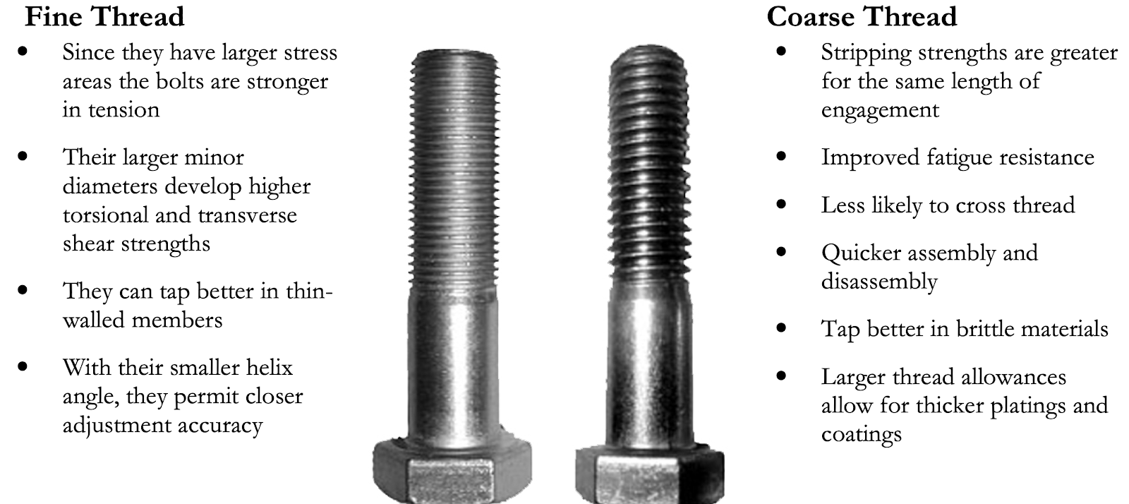
Image Credit: Fastenal - Use case will determine the specific hardware
An important note is that the DoD does not recognize the first number (8) since that is a commercial classification. Instead, the callout would be the nominal diameter so the actual callout for the screw is 0.164-32 UNC 2A followed by the rest of the particulars. (The .164 is a fraction of an inch) Fine pitch threads would be called out as .164-36 UNF instead of UNC. The 36 accounts for the extra threads per inch of fine thread types. Calling out the number 8 instead of the nominal diameter was one of two things that my first military document package got marked up when the auditors came through.
While I’m baring my soul, I may as well discuss the other concern about the Mil-STAR documentation. After the audit, Merrill, my manager said, “John, we got tagged in the audit for having ‘Methodized drawings’. What does that mean?”
I said, “You know those notes that Eric (the Manufacturing Engineer in the Assembly dept.) keeps asking for that I push back on but we end up putting them on the assembly drawing anyway?”
Merrill: Yeah.
Me: That’s a methodized drawing.
Merrill: Oh!
Eric wanted to make the process easier for the assemblers and requested that instructions be added to the assembly drawings. Additions were like torque settings for the air-drivers or solder tip temperature; that sort of stuff. In spite of my objections, the powers that be sided with Manufacturing. After being proven right in the audit, Merrill gave me the additional responsibility of checking everyone else’s drawings. They were all hit pretty hard by the Army Sergeants who came out to inspect our drawings.
Image Credit: DefPost - MilSTAR was more than a satellite program. (One of those birds was lost in space back in ‘99 due to a documentation error!)
The takeaway is that these are inspection documents. If you can compare the assembly to the drawing and be sure that everything is as described, then you’re good. Process documents cover the process and the drawings are “What is” not “How to”. The other takeaway is that you don’t want to be a drawing checker - unless you’re into that sort of thing.
The Sergeants never looked at the actual product; they just wanted to be sure that the entire program could be resuscitated from the microfilm. Their concern was continuity of readiness if the company happened to be vaporized along with the high value targets in the Bay Area. The Cold War was a real thing in their minds. It was a simpler world with far fewer recognized threats. Search and Target Acquisition Radar was a tool to take down the bad guys. Today, it’s not so simple so the solutions are more complex. Class 3 PCBs are extra robust for a reason.