OrCAD Capture 2: Creating Parts
This tutorial demonstrates several ways you can create and add parts to a Capture library. After you complete this tutorial, you will be able to:
- Copy library parts and paste them into a new design library
- Rename and edit a library part
- Create a new part and add it to your design library
If you would like to follow along with this tutorial, you can visit our walk-through page to view video tutorials and download design files .
To follow the instructions presented in this tutorial, continue using the design you completed in Capture Walk-through 1 or use the included design file, CAPTURE TUTORIAL 2_CREATING PARTS.DSN.

Select File > Open > Library from the menu.

Use the following path to access the default libraries provided in Capture: C:\Cadence\SPB_22.1\tools\capture\library

- Open the CAPSYM.OLB library.

Note: Click on the arrow located in the right of the library, to change the view of the window: docked, floating or a tabbed document.

Select Ground_Power and Titleblock3 in the capsym.olb library.
Note: To select multiple items, hold down the CTRL on the keyboard and select the desired items.
Use CTRL+C on the keyboard to copy.

In the Capture Tutorial project hierarchy, right click on the Capture Tutorial library and select Paste.

Right click on GND_POWER and select Rename. Rename the part to GND.
Right click on Titleblock3 and select Rename. Rename the part to TitleBlock.

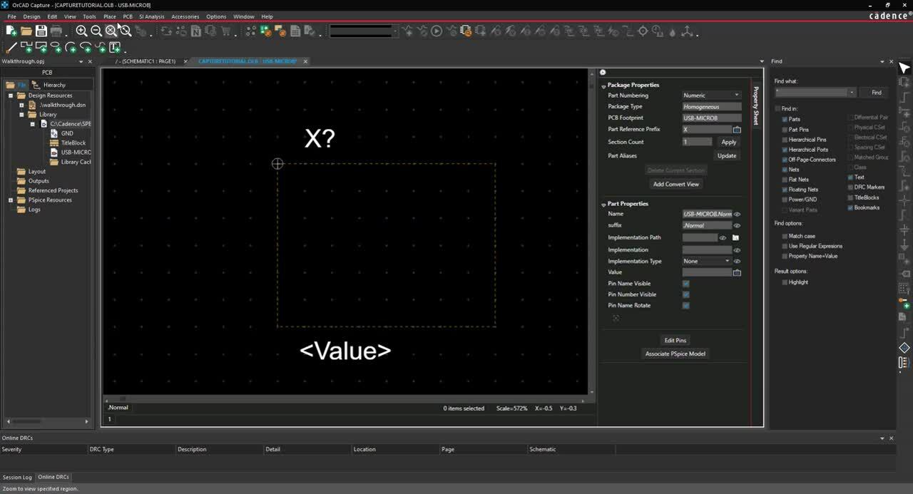
Right click on the Capture Tutorial library and select New Part.

Enter the following information:
- Name: USB-MicroB
- Part Reference Prefix: X
- PCB Footprint: USB-MicroB
Note: Use TAB on the keyboard to quickly go to the next field.
Click OK.

Click the boundary part and drag the vertex to resize the boundary box.
Select Place > Rectangle from the menu.
Click and drag to draw the rectangle.
Right-click and select End Mode (ESC).
Select Place > Pin from the menu.

Enter the pin properties below in the Place Pin dialog window:
- Name: GND
- Number: GND
- Shape: Short
- Type: Input
- Click OK.
- Click a location on the part boundary to place the pin.
- Use Shift+G on the keyboard to re-open the Place Pin window. Enter the values for the next pin.
- Continue placing pins using the pin properties below.

Note: When the pin ends in a number the next pin placed will be sequential. You can continue to click and place MT1 to MT4 and P_1 to P_2 without editing properties between pins.
Right Click and select End Mode when finished (ESC).

- In the Property Sheet, de-select the Pin Name Visible check box.
- Select the Value text. Right click and select Rotate.
- Click and drag the text to a new location.
- Double click the text.
- Change the value to USB-B and Enter.

- Right click the part tab. Select Save and Close.
Note: A part can be viewed and edited by double clicking the name in the library. In the Property Sheet, select Edit Pins to edit all the pins in the part.